Circuit for detection and control of LED string operation

a technology for led strings and circuits, applied in the direction of discharge tubes/lamp details, electric discharge lamps, discharge tubes/lamp details, etc., can solve the problems of reducing the operating life of a battery power source, excessive device heating, and increasing the power dissipation in the current sink of all other channels, so as to increase the value of increase the operating voltage, and increase the effect of the value of the vch for all other channels

Inactive Publication Date: 2012-10-25
MICROCHIP TECH INC
View PDF8 Cites 25 Cited by
  • Summary
  • Abstract
  • Description
  • Claims
  • Application Information

AI Technical Summary

Benefits of technology

[0009]Consider the case when an LED string has a device which has a large operating voltage drop, or is an open circuit, causing the corresponding channel voltage VCH to drop towards zero. The minimum voltage feedback value to the power source 13 will correspondingly fall to zero, causing the power source 13 to increase its output V1 until the minimum channel voltage is brought back to its desired value. As a result, the value of VCH for all other channels will be increased, causing the power dissipation in the current sinks of all other channels to increase. This can lead to excessive power dissipation in the overall system used to create the current sinks, damaging the integrated circuit. In the case where an open device is present, the voltage source 13 may increase its output V1 until some device in the system suffers breakdown and damage due to excessive applied voltage. This can result in catastrophic failure of the entire LED illumination system. Usually a separate, independent circuit is used to limit the voltage excursion of the voltage source 13 under these conditions to prevent catastrophic failure.
[0010]Therefore, one objective of the voltage detector 14 is to be able to determine if a large voltage drop string STR is present, and isolate it from the operation of the remainder of the system to prevent power loss, overheating, or catastrophic damage.

Problems solved by technology

If the integrated circuit system is dissipating excessive power as heat, this power does not contribute to the light output of the LEDs, but it will reduce the operating lifetime of a battery power source.
If this causes the voltage across one or more channel current sinks to be too large, the power lost in the current sinks will cause excessive device heating.
As a result, the value of VCH for all other channels will be increased, causing the power dissipation in the current sinks of all other channels to increase.
This can lead to excessive power dissipation in the overall system used to create the current sinks, damaging the integrated circuit.
This can result in catastrophic failure of the entire LED illumination system.
If a sufficient number of these devices are present in a particular string, then the corresponding current sink (1, for example) would have excessive power dissipation.
If several LEDs have failed, this power dissipation can become sufficient to endanger the continued operation of the integrated circuit system.
As an example, if some of the LEDs in string STR1 (item 10) have less voltage drop than normal, the voltage VCH1 may cause excessive power dissipation.

Method used


Image

  • Circuit for detection and control of LED string operation
  • Circuit for detection and control of LED string operation
  • Circuit for detection and control of LED string operation

Examples


Embodiment Construction

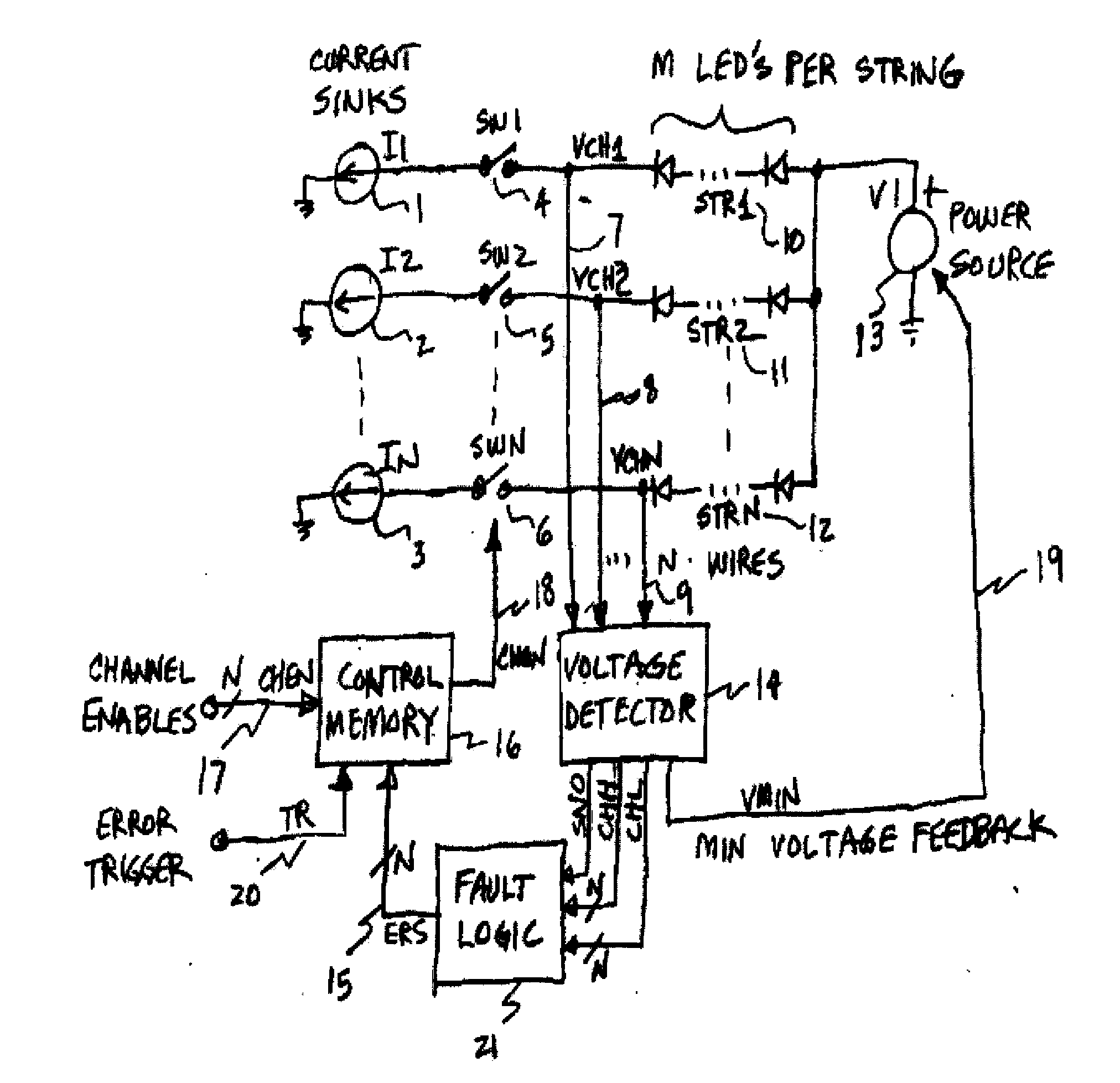
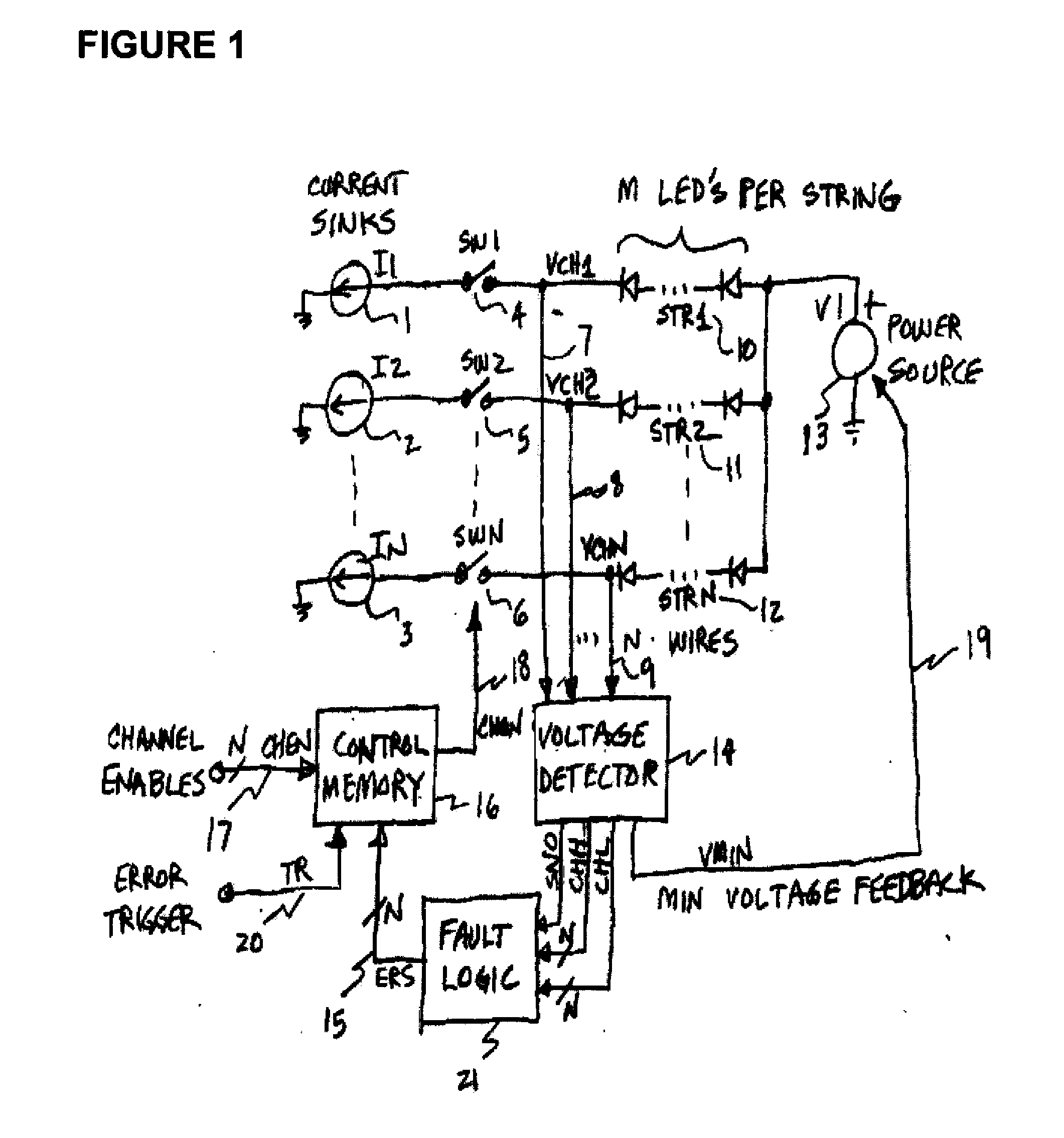
[0024]Operation of the voltage detector in FIG. 2 begins with the channel voltage inputs VCH on wire group 31, corresponding to wires 7 through 9 in FIG. 1. These voltages go into a maximum detector 34, together with the CHON signals 33. The maximum detector determines the voltage value of the channel with the largest voltage VCH, and which is indicated as active by the associated channel on signal CHON. If a particular channel has its CHON signal off or inactive, then the associated VCH signal will not be used in determining the value of the maximum voltage output VMAX on wire 35.

[0025]FIG. 3 shows a typical means for making the maximum voltage detector 34 of FIG. 2. There are many ways known in the state of the art for making a circuit which is capable of selecting and outputting the largest of a set of input voltages. This figure shows one method which has been used to make the maximum detector. Operation begins with the input signal set consisting of N wires carrying signals VCH...


PUM


Abstract

A circuit is disclosed for determining which of a multiplicity of LED strings in an illumination system has a fault. A group of circuits determines the maximum, minimum, midpoint between maximum and minimum, and average voltage of the group of LED string voltages in use, and examines the statistical properties of the LED string voltages. Comparators are used to find the strings which have the highest and lowest operating voltages, and to compare the midpoint and average voltages to determine whether the highest or lowest voltage string is responsible for causing a fault in the illumination system operation. Memory means are used to keep the said determined string turned off to prevent faulty operation.

Description

FIELD OF THE INVENTION [0001]A circuit for detection and control of LED strings is disclosedBACKGROUND AND SUMMARY OF THE INVENTION [0002]Consider a power control system for light emitting diodes (LED) as shown in FIG. 1 (which depicts an embodiment to be discussed below). The purpose of this system is to provide controlled current for operation of the N LED strings STR denoted as 10 through 12. To this end, a multiplicity of N current sinks I1 through In denoted as 1, 2, and 3 are used to control the current through the LED strings. These current sinks may have different values, or may be operating at different times, without affecting the considerations being discussed below. A series combination of a current sink 1, a switch 4, and an LED string 10, for example, is denoted as a channel. The voltage source V1 is optimally chosen to have a value just large enough that all of the current sinks operate correctly. If the channel voltages VCH1, VCH2, through VCHn are of sufficient magn...

Claims


Application Information

Patent Timeline
Patent Type & Authority Applications(United States)
IPC IPC(8): H05B37/02H05B37/03H05B44/00
CPCH05B33/0893H05B45/58
Inventor WALKER, JAMES T.
Owner MICROCHIP TECH INC
Why Eureka
Try Eureka