
Pluggable transceiver module

a transceiver module and module technology, applied in the field of pluggable transceivers, can solve the problems of affecting the operation of the base unit, the power supply of the board or the module connected to the unit, and the inability to properly design, so as to prevent damage to components within the module, the effect of controlling in-rush current more effectively

Active Publication Date: 2010-09-28
SUMITOMO ELECTRIC DEVICE INNOVATIONS U S A
View PDF8 Cites 2 Cited by
  • Summary
  • Abstract
  • Description
  • Claims
  • Application Information

AI Technical Summary

Benefits of technology

[0011]It is also another object of the present invention to provide a module for use in an optical fiber transmission system with means for slowly ramping up the power level in such module when plugged into the host unit.
[0014]It is another object of the present invention to provide a transceiver for use in a data transmission system with a programmable power ramp-up circuit to prevent voltage drop in the host system when the transceiver is activated.
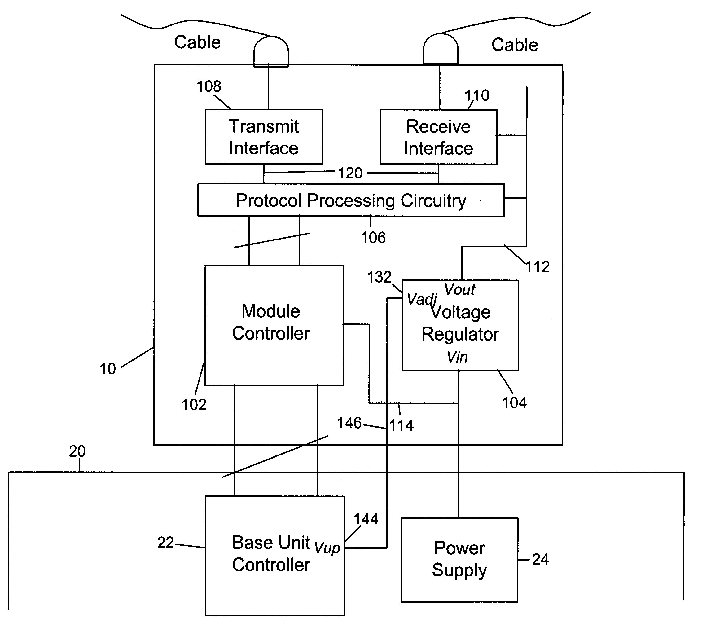
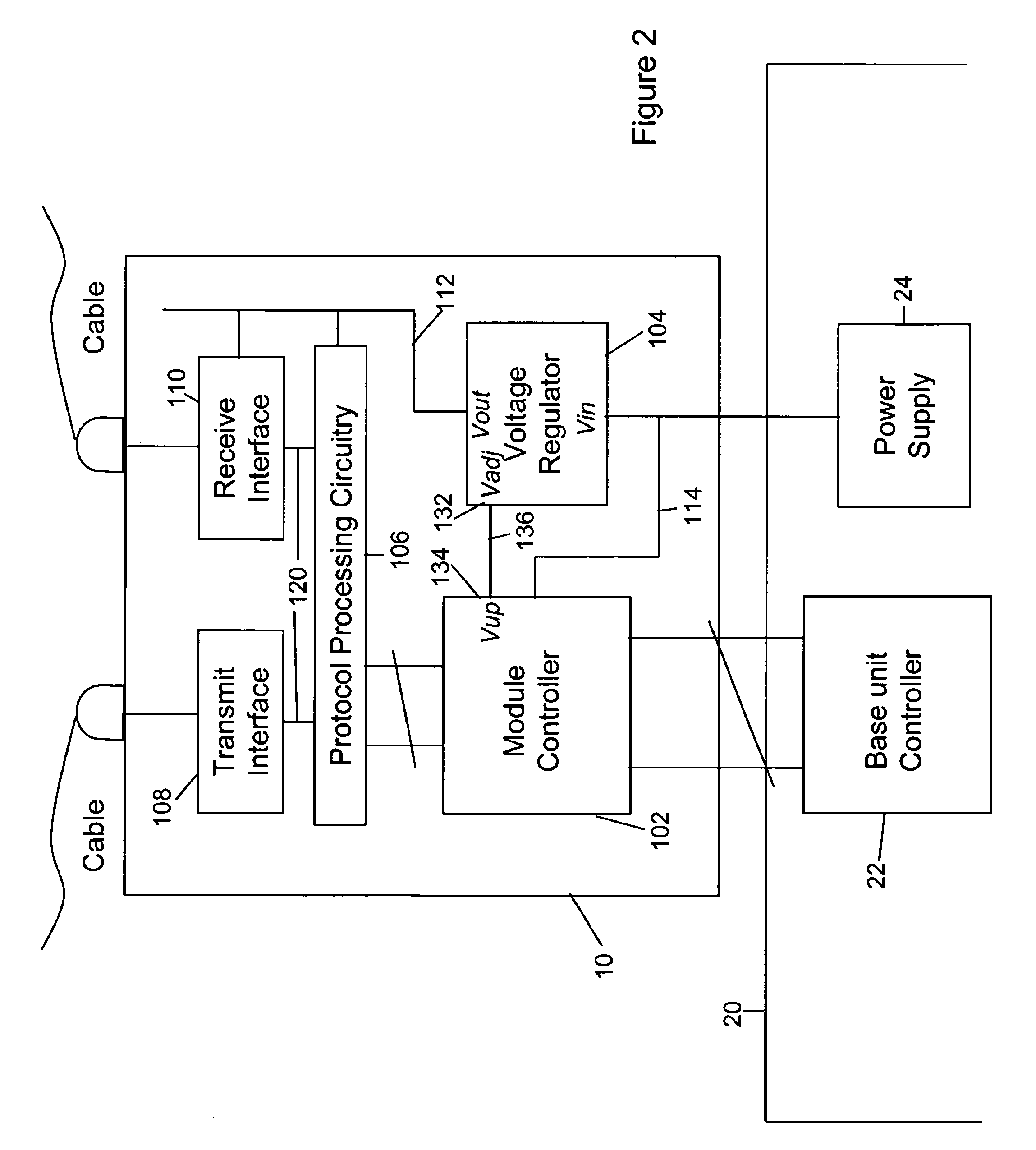
[0016]Briefly, and in general terms, the present invention provides a pluggable module which may be connected to the backplane or other connection interface of a unit so as to provide additional functionality thereto, the pluggable module being arranged to draw electrical power from the unit. In order to prevent excessive in-rush current on connection the module is provided with power control circuitry which is adapted to incrementally increase the supply voltage to components within the module in a manner so as to avoid power supply glitches in the unit into which it is plugged, such as a substantial voltage drop, and / or excessive current flow.
[0019]The power control circuitry within a module according to an embodiment of the invention preferably adjusts the supply voltage to the components within the module during a start-up phase only of the module, after initial module power-on. Thereafter the adjustment is preferably not provided. Moreover, preferably the power control circuitry is formed from components already existing in the module, such as a voltage regulator and module controller such as a microprocessor, a feedback input of the voltage regulator having a control signal applied thereto from the microprocessor whereby to effect said adjustment. The microprocessor also controls other components within the module in a conventional manner. The use of the existing components, however, allows for more efficient use of board space, an important consideration in high-density designs.
[0020]The power control circuitry preferably, within embodiments of the invention, adjusts the supply voltage according to a programmable profile. Such a feature allows for the supply voltage to be controlled to achieve a desired result, such as to, for example, control in-rush current more effectively, and / or prevent damage to components within the module.

Problems solved by technology

However, many pluggable modules, and in particular those containing low voltage components with associated large capacitors, can, if not properly designed, draw a large amount of in-rush current at the moment of connection to a system.
This large in-rush current can cause a momentary drop in the base unit power supply voltage, causing glitches in the power supply of the base unit into which the module has been plugged.
Such glitches can cause other boards or modules connected to the unit to malfunction, and in a worst case can cause complete system shutdown.
In addition, as well as causing problems in a unit into which a pluggable module is plugged, the large in-rush current which can occur can also damage components within the module itself.
Moreover, the LTC 4216 has typically not been widely used in pluggable module applications, because it requires a relatively large area of PCB space for itself and its supporting components.
The additional PCB space thus required can be very hard to accommodate in high density designs, which are almost always used for small pluggable modules.
However, this degree of start up ramp is often too short a time period to avoid the problems of in-rush current noted above.

Method used


Image

  • Pluggable transceiver module
  • Pluggable transceiver module
  • Pluggable transceiver module

Examples


Embodiment Construction

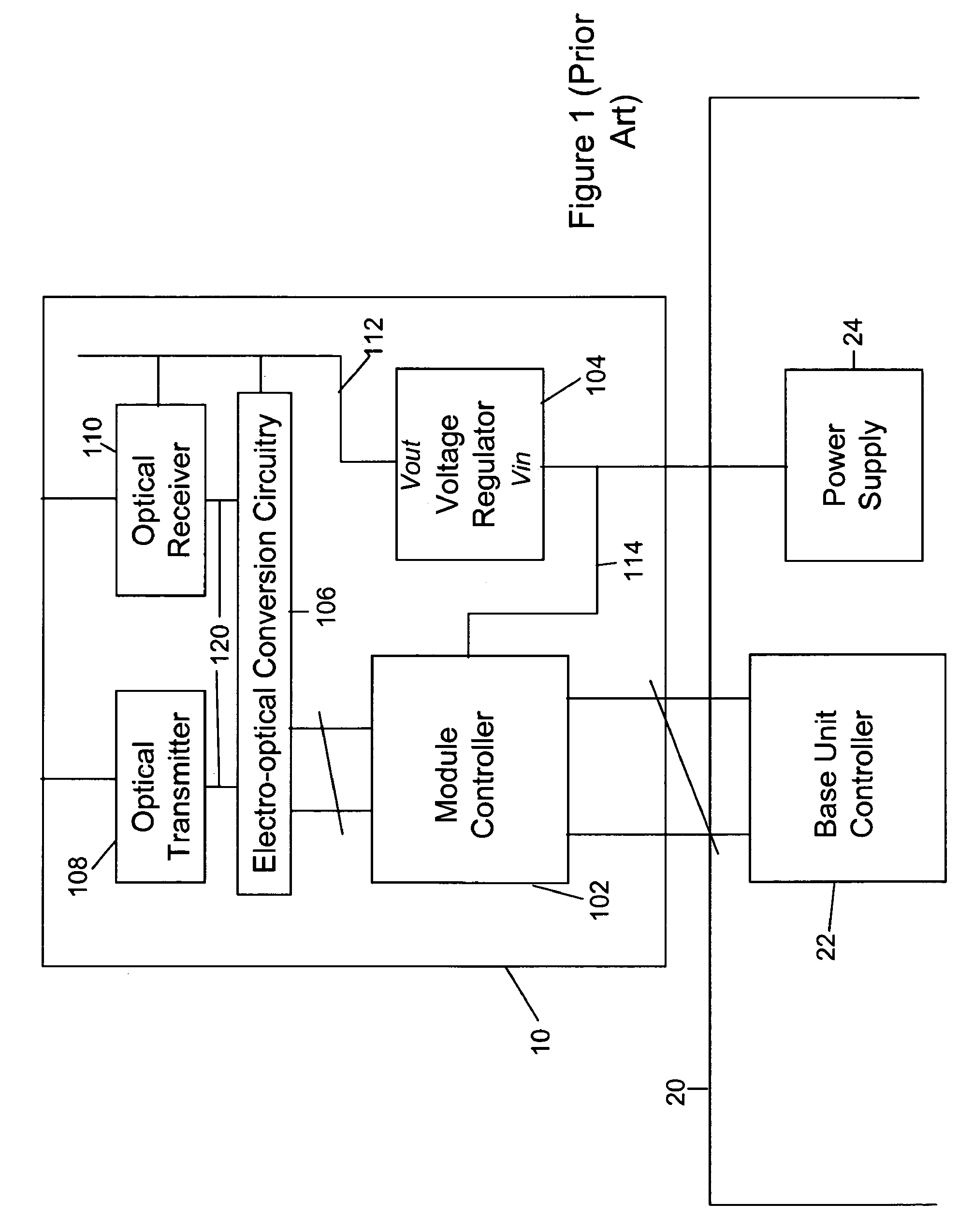
[0032]For the purposes of understanding the embodiments of the invention to be described, it will be helpful first of all to describe a conventional prior art pluggable module, to which the invention may be applied.

[0033]With the above in mind, FIG. 1 is a block diagram of a prior art conventional pluggable module. Embodiments of the invention to be described particularly relate to pluggable electrical or optical transceiver modules, being modules which are releasably connectable to a router or switch in a communications network. Optical transceivers include electro-optical conversion devices (such as lasers and photodiodes) in order to convert data to be transmitted over the communications network between the electrical and optical domains to allow transmission over an optical fiber.

[0034]As shown in FIG. 1, a pluggable optical module 10 comprises a module controller 102 which would typically be a microprocessor. Additionally provided is a voltage regulator 104, which receives a su...


PUM


Abstract

A pluggable module connected to the backplane or other connection interface of an information system unit so as to provide additional functionality thereto (such as a communications interface to an electrical or fiber optics cable), and arranged to draw electrical power from the system. In order to prevent excessive in-rush current on connection, the module is provided with power control circuitry which is adapted to incrementally increase the supply voltage to components within the module in a manner so as to avoid power supply glitches in the system, such as a substantial voltage drop, and / or excessive current flow.

Description

BACKGROUND OF THE INVENTION[0001]1. Field of the Invention[0002]The present invention relates to a pluggable transceiver module for releasable connection to a base unit in a computer network, and in particular a pluggable module which has power control circuitry which can be used to adjust the supply voltage supplied to at least a subset of components within the module. The invention also relates to a combination comprising such a pluggable transceiver module and a base unit into which it may be releasably connected.[0003]2. Description of the Related Art[0004]Pluggable transceiver modules are used extensively in large router and switching systems, in information storage systems, data communication networks, as well as other systems. It is usually intended that such modules are able to be inserted into the receiving interface for the module in the router or switch base unit without disrupting any other modules which may be connected to the base unit, or disrupting the base unit itse...

Claims


Application Information

Patent Timeline
Patent Type & Authority Patents(United States)
IPC IPC(8): G06F1/00
CPCG06F1/26
Inventor WANG, XIAOZHONGLAU, EDMONDLAU, BILL
Owner SUMITOMO ELECTRIC DEVICE INNOVATIONS U S A
Learn More