

Unit-magnification catadioptric and catoptric projection optical systems
Patent Information
- Authority / Receiving Office
- US · United States
- Patent Type
- Applications(United States)
- Current Assignee / Owner
- COHERENT INC
- Publication Date
- 2012-10-25
Smart Images
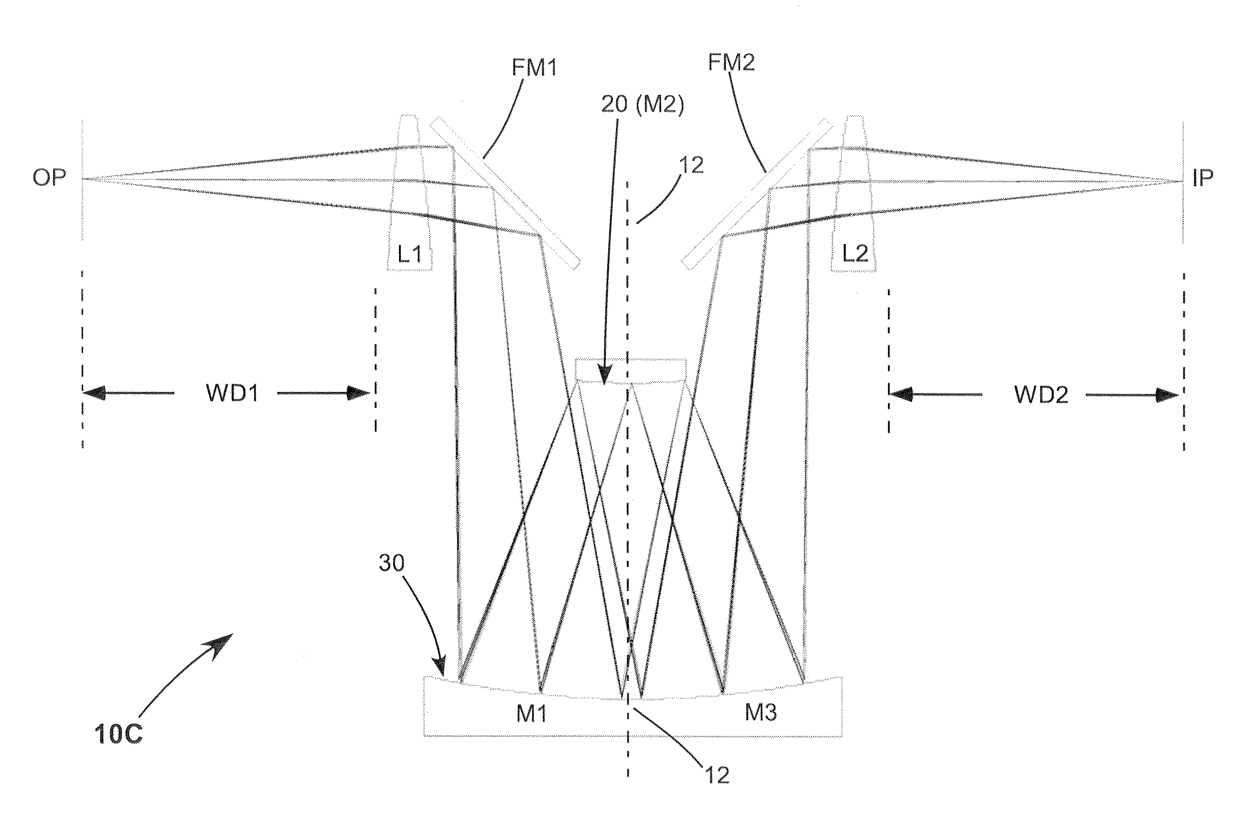
Figure 1 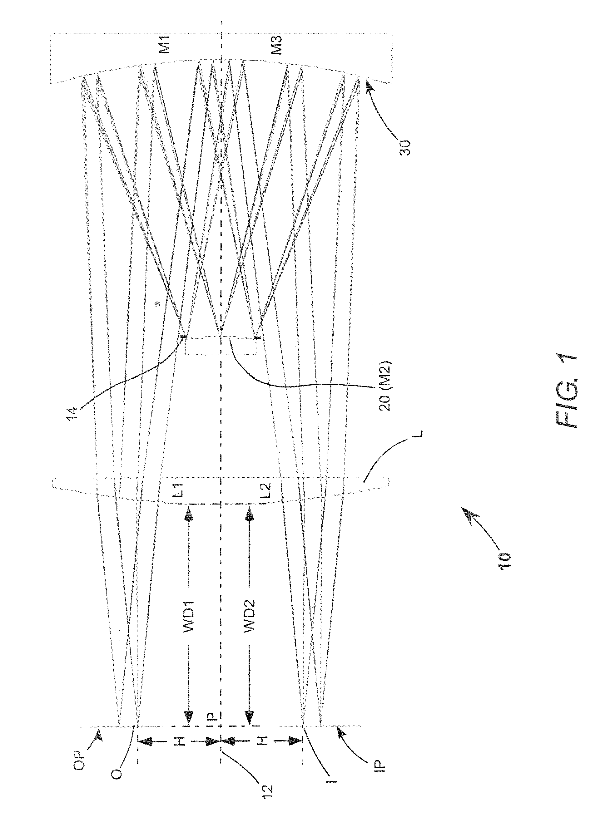
Figure 2 
Figure 3
Abstract
Description
PRIORITY CLAIM
[0001] This application claims priority of U.S. Provisional Application No. 61 / 478,362 filed Apr. 22, 2011, assigned to the assignee of the present invention, and the complete disclosure of which is hereby incorporated herein by reference.TECHNICAL FIELD OF THE INVENTION
[0002] The present invention relates in general to projection optical systems. The invention relates in particular to large-field catadioptric and catoptric projection optical systems for forming an image of an object at unit magnification.DISCUSSION OF BACKGROUND ART
[0003] Various unit-magnification optical imaging systems are known in the patent literature. Patents related to unit-magnification optical system comprising a concave spherical mirror and a convex spherical mirror include U.S. Pat. No. 3,748,015, U.S. Pat. No. 4,293,186, U.S. Pat. No. 4,711,535, and U.S. Pat. No. 4,796,984.
[0004] U.S. Pat. No. 3,748,015 describes a unit-magnification imaging catoptric system comprising a concave spherical mino...