
System and method for managing reduced pressure delivered to a tissue site

a tissue site and reduced pressure technology, applied in the field of tissue treatment, can solve the problems of affecting the ability of tissue site tissue to be used, affecting the effectiveness of tissue treatment, and reducing the ability of tissue treatment systems to be used, so as to achieve the effect of reducing pressure and delivering pressur

Active Publication Date: 2012-10-25
3M INNOVATIVE PROPERTIES CO
View PDF2 Cites 108 Cited by
  • Summary
  • Abstract
  • Description
  • Claims
  • Application Information

AI Technical Summary

Benefits of technology

[0127]It should be apparent from the foregoing that an invention having significant advantages has been provided. While the invention is shown in only a few of its forms, it is not just limited but is susceptible to various changes and modifications without departing from the spirit thereof.

Problems solved by technology

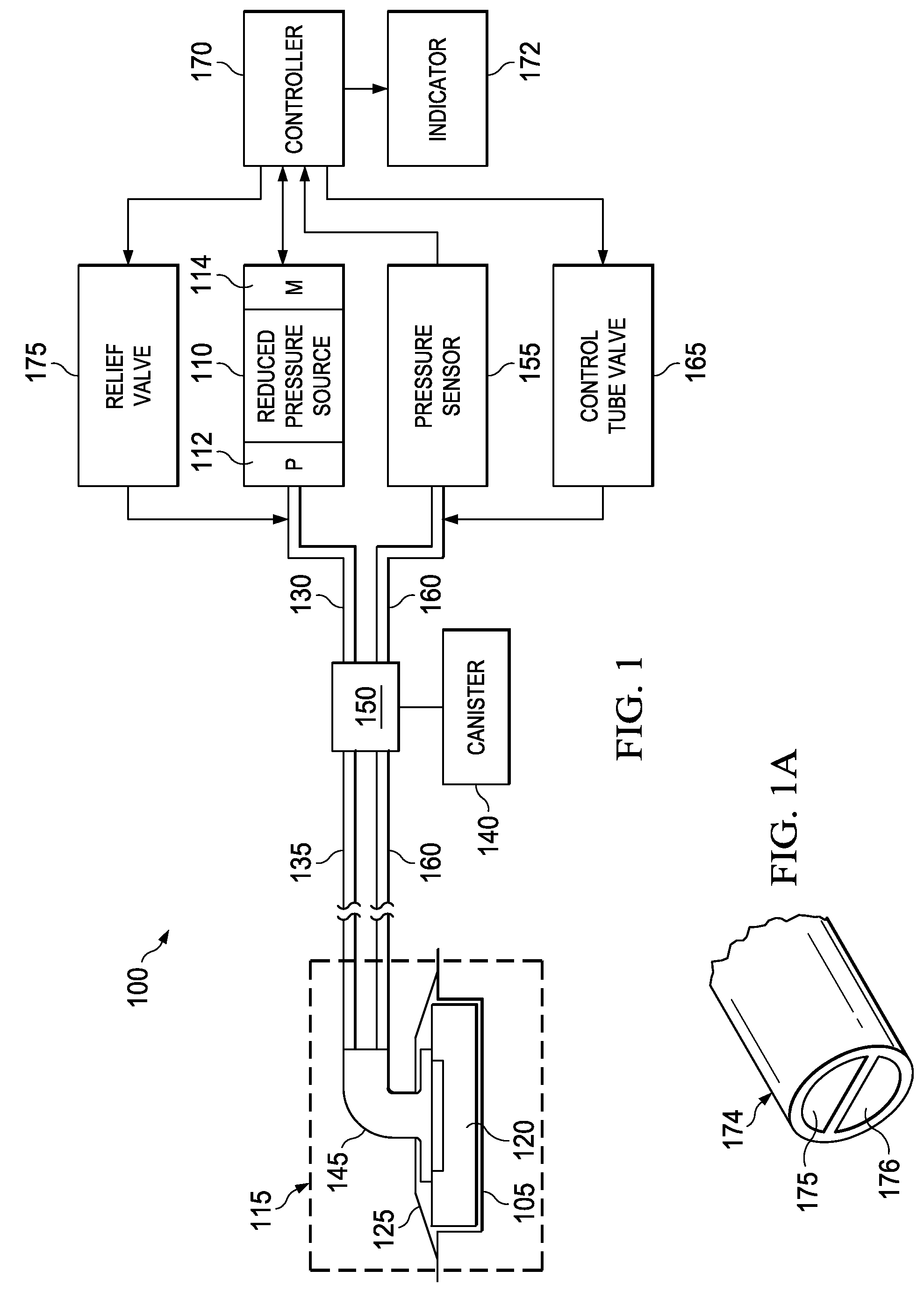
For example, a leak or blockage in the tube that connects a reduced pressure source, such as a vacuum pump, to the tissue site may disrupt the reduced pressure treatment being administered to the tissue site.
However, the two sensors used by current differential pressure control systems increase the size, weight, cost, and complexity of such systems.
The additional components required by current differential pressure control systems reduce the ability of those systems to be used to treat low-severity wounds and wounds on ambulatory patients.
In addition, the additional components required by such systems increase the obtrusiveness and weight of the reduced pressure treatment system, thereby increasing the discomfort and limiting the mobility of the patient.
Discrete pressure sensors for providing feedback to the system are not only expensive, but also increase the potential for wound infection as another input connected to the pneumatic circuit of the negative pressure wound care system.

Method used


Image

  • System and method for managing reduced pressure delivered to a tissue site
  • System and method for managing reduced pressure delivered to a tissue site
  • System and method for managing reduced pressure delivered to a tissue site

Examples


Embodiment Construction

[0023]In the following detailed description of the preferred embodiments, reference is made to the accompanying drawings that form a part hereof, and in which is shown by way of illustration specific preferred embodiments in which the invention may be practiced. These embodiments are described in sufficient detail to enable those skilled in the art to practice the invention, and it is understood that other embodiments may be utilized and that logical structural, mechanical, electrical, and chemical changes may be made without departing from the spirit or scope of the invention. To avoid detail not necessary to enable those skilled in the art to practice the invention, the description may omit certain information known to those skilled in the art. The following detailed description is, therefore, not to be taken in a limiting sense, and the scope of the present invention is defined only by the appended claims.

[0024]The illustrative embodiments described herein provide and apparatus a...


PUM


Abstract

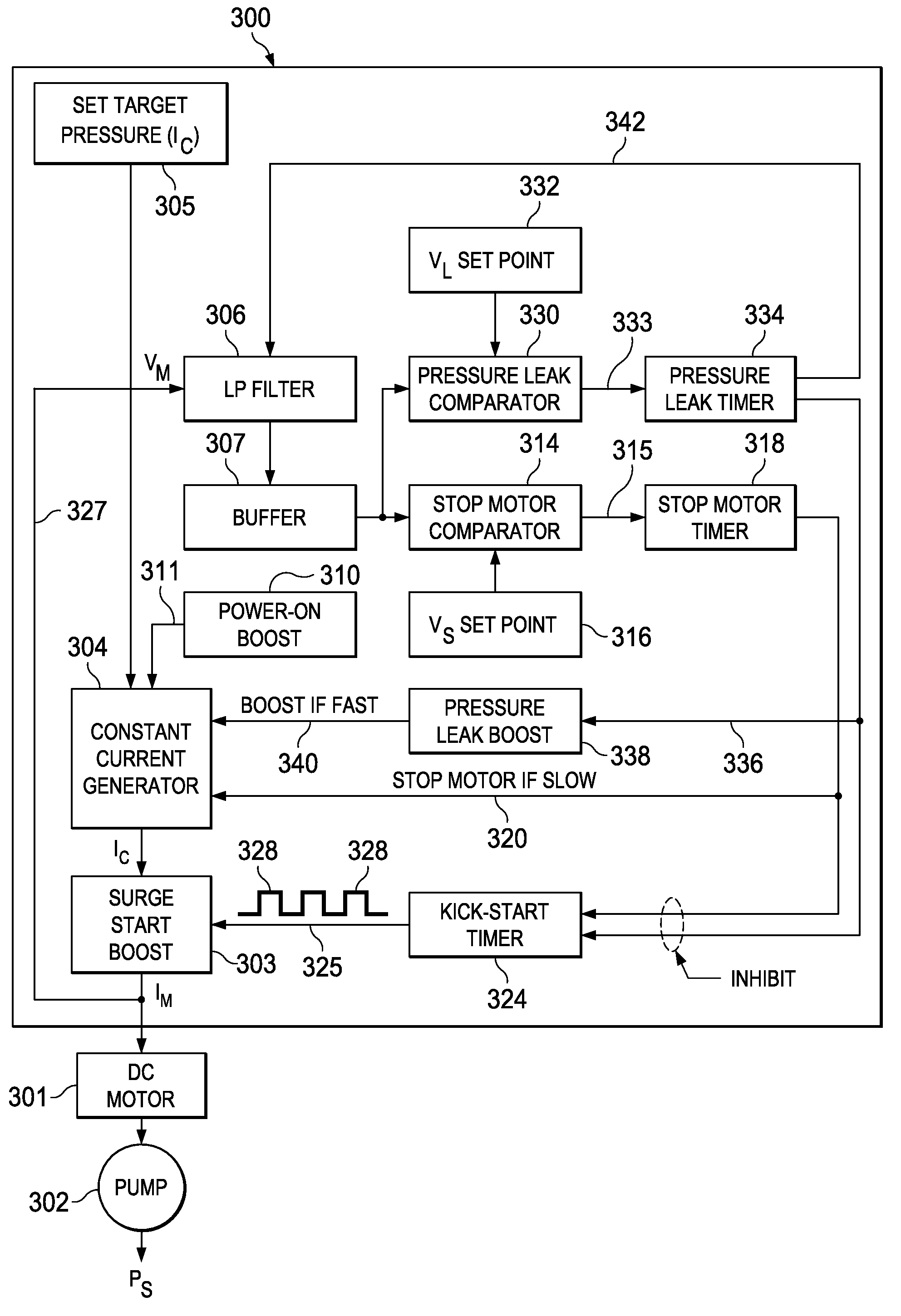
An apparatus and method for managing reduced pressure at a tissue site are disclosed. The apparatus comprises a pump for supplying reduced pressure to the tissue site, a motor coupled to the pump to propel the pump, and a drive system electrically coupled to the motor that includes a power source that provides a source of direct current power to the motor during an operational period at a substantially constant current and of sufficient magnitude to supply a targeted reduced pressure during the operational period. The drive system also includes a controller that monitors the pump's loading on the motor by measuring the voltage across the motor to determine whether the motor voltage remains within a predetermined operational range of voltages necessary for maintaining the reduced pressure supplied by the pump proximate to the targeted reduced pressure without directly measuring the reduced pressure using a pressure sensor.

Description

RELATED APPLICATIONS[0001]The present invention claims the benefit, under 35 U.S.C. §119(e), of the filing of U.S. Provisional Patent Application Ser. No. 61 / 477,406, filed 20 Apr. 2011, which is incorporated herein by reference for all purposes.BACKGROUND OF THE INVENTION[0002]1. Field of the Invention[0003]The present invention relates generally to the field of tissue treatment, and more specifically to a system and method for applying reduced pressure delivered to a tissue site.[0004]2. Description of Related Art[0005]Clinical studies and practice have shown that providing a reduced pressure in proximity to a tissue site augments and accelerates the growth of new tissue at the tissue site. The applications of this phenomenon are numerous, but application of reduced pressure has been particularly successful in treating wounds. The treatment of wounds using reduced pressure is sometimes referred to in the medical community as “negative pressure tissue treatment,”“reduced pressure t...

Claims


Application Information

Patent Timeline
Patent Type & Authority Applications(United States)
IPC IPC(8): A61M1/00
CPCA61M1/0088A61M1/0031A61M1/742A61M1/92A61M1/962A61M1/80
Inventor LOCKE, CHRISTOPHER BRIANBLANDFORD, DAVID ROBSONCOULTHARD, RICHARD DANIEL JOHN
Owner 3M INNOVATIVE PROPERTIES CO
Learn More