Electric motor

a technology of electric motors and motors, applied in the direction of current collectors, dynamo-electric machines, dc interrupters, etc., can solve the problems of low motor production efficiency, and achieve the effect of higher production efficiency

Inactive Publication Date: 2012-11-01
JOHNSON ELECTRIC SA
View PDF7 Cites 2 Cited by
  • Summary
  • Abstract
  • Description
  • Claims
  • Application Information

AI Technical Summary

Benefits of technology

[0016]In the above mentioned embodiments of the present invention, as the poles of the rotor are made of magnetically conductive material, the magnetizing step during manufacture is omitted and, compared to current electric motors, the production efficiency is higher.

Problems solved by technology

However, the permanent magnet of the rotor requires a magnetizing step in the manufacturing process, which lowers the production efficiency of the motor.

Method used


Image

  • Electric motor
  • Electric motor
  • Electric motor

Examples


Embodiment Construction

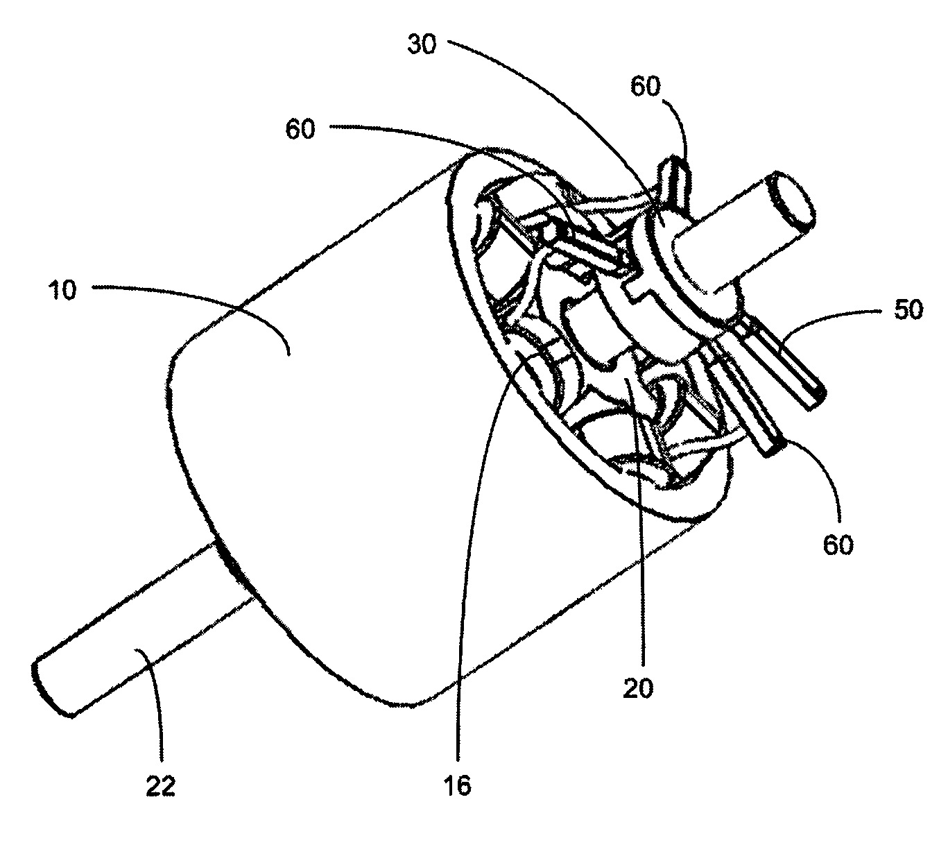
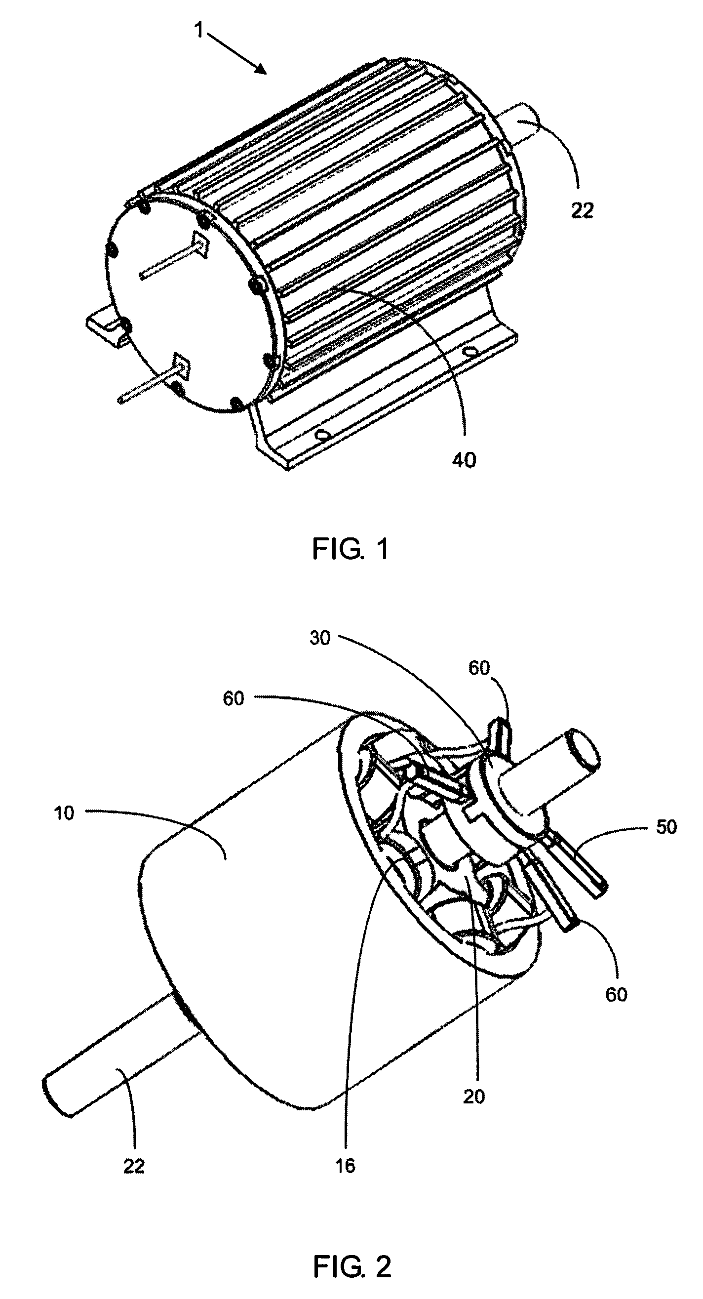
[0030]Referring to FIGS. 1 to 5, a brush direct current motor 1, according to a first embodiment of the present invention, includes a stator 10, a rotor 20, a commutator 30, a casing 40, a first brush 50, and a number of second brushes 60. A brush direct current motor refers to a DC motor which has a commutator and a number of brushes arranged to make sliding electrical contact with the commutator.

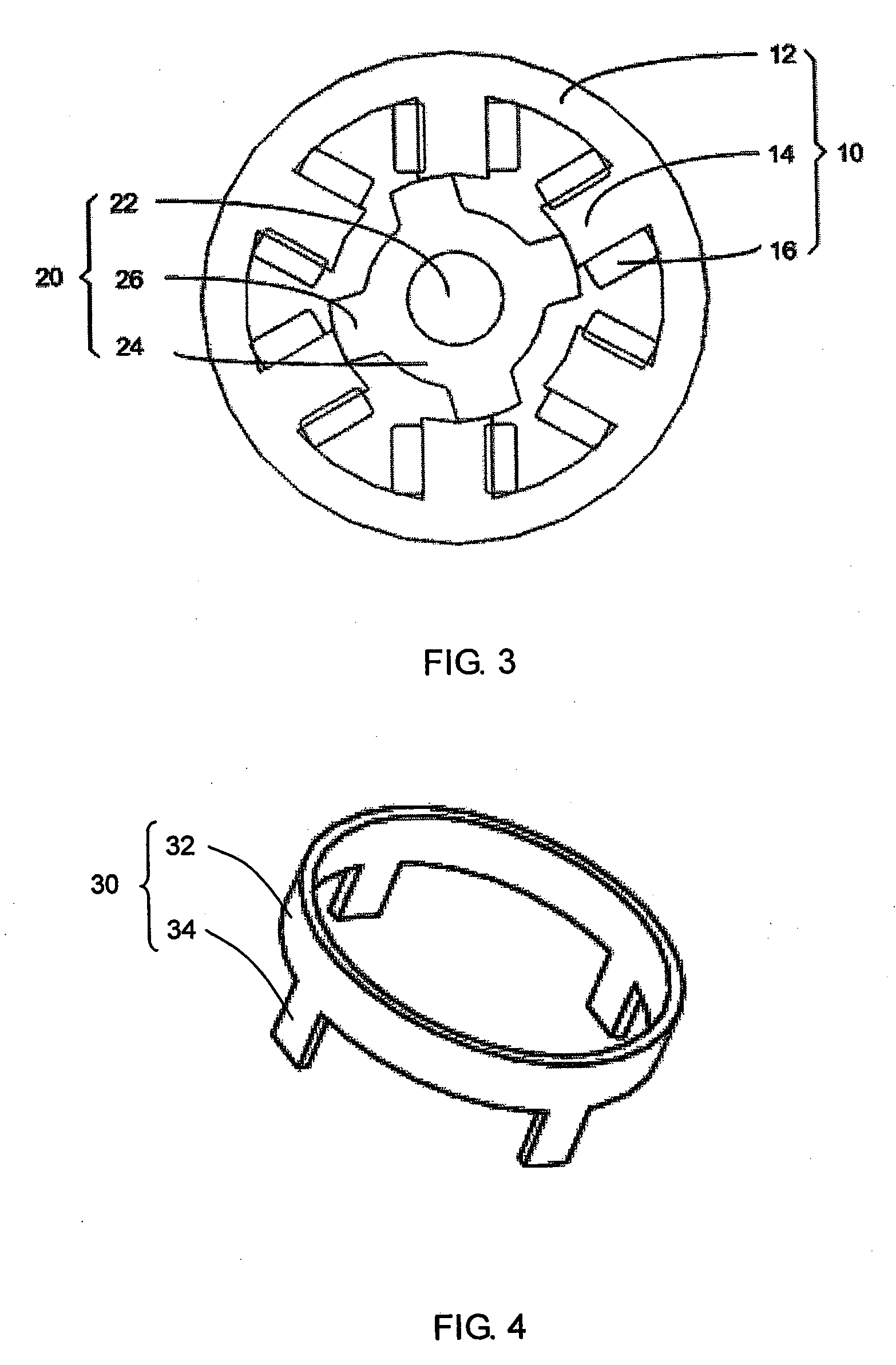
[0031]The stator 10 includes a circular yoke 12, a number of teeth 14, and a number of coils 16. The yoke 12 is fixed to the inner surface of the casing 40, preferably as a press fit. The teeth 14 protrude from the inner surface of the yoke 12. The coils 16 correspond to a number of phases and are wound around corresponding teeth 14. In the present embodiment, the stator 10 has six teeth 14 and there are 6 coils 16 are made of aluminum wire. Each phase comprises two coils wound about two diagonally opposite teeth. The coils may be connected in series or parallel, depending on the applicati...


PUM


Abstract

A brush direct current motor has a stator with a plurality of coils that correspond to a number of stator windings, a rotor with a number of poles, and a commutator. The commutator is connected to a first terminal of a direct current power source to convert the power into N phase alternating current. One end of each stator winding is connected to a respective phase of the alternating current via a brush and the other ends of the stator windings are connected to the second terminal of the direct current power source.

Description

CROSS REFERENCE TO RELATED APPLICATIONS[0001]This non-provisional patent application claims priority under 35 U.S.C. §119(a) from Patent Application No. 201110109452.X, filed in The People's Republic of China on Apr. 28, 2011.FIELD OF THE INVENTION[0002]This invention relates to electric motors and in particular, to a direct current motor having a commutator and a rotor having poles made of magnetically conductive material.BACKGROUND OF THE INVENTION[0003]Direct current electric motors having a permanent magnet rotor, wound stator coils, a commutator and brushes are generally known as shown in U.S. Pat. No. 6,396,175. The commutator is used to convert the direct current power into three phase alternating current power to supply the stator coils. Current designs, like the mentioned patent, usually employ a permanent magnet rotor. However, the permanent magnet of the rotor requires a magnetizing step in the manufacturing process, which lowers the production efficiency of the motor.[00...

Claims


Application Information

Patent Timeline
Patent Type & Authority Applications(United States)
IPC IPC(8): H02K23/00
CPCH01R39/04H02K25/00H02K23/36H02K23/00H02K13/04H02K13/00H02K23/18H02K13/006H02K23/20
Inventor LI, YUELIU, LI SHENGQI, YONG QINGZHANG, HONG JIAN
Owner JOHNSON ELECTRIC SA
Why Eureka
Try Eureka