Electronic circuits and methods for driving a diode load

a technology of electronic circuits and diodes, applied in the direction of electric variable regulation, process and machine control, instruments, etc., can solve the problems of loss of fast load current control that is useful for pwm brightness control and can be achieved with the use of such current regulator circuits, and achieve the effect of more rapid flow

Active Publication Date: 2012-11-01
ALLEGRO MICROSYSTEMS INC
View PDF6 Cites 31 Cited by
  • Summary
  • Abstract
  • Description
  • Claims
  • Application Information

AI Technical Summary

Benefits of technology

[0009]With these arrangements, control of the LED brightness by the PWM signal occurs more quickly than otherwise possible. This is because the load disconnect switch opens the load current path when the converter turns off, thereby promptly terminating the load current flow (rather than waiting for the converter output capacitor to discharge). Opening the load current path in this manner also causes the load current to start flowing more quickly when the converter is next turned on since the converter output voltage is stored on the output capacitor when the load current path is opened (rather than waiting for the output capacitor to charge).

Problems solved by technology

When the load contains multiple parallel strings of LEDs, the driver circuit often requires complex current regulator circuits to generate identical currents through each LED string.
Generating identical LED currents is complicated by the fact that the forward voltage of the LED strings can differ.
Thus, while the elimination of costly and complex current regulator circuits in a single string LED driver is desirable, the fast load current control that is useful for PWM brightness control and that can be achieved with the use of such current regulator circuits is also lost.

Method used


Image

  • Electronic circuits and methods for driving a diode load
  • Electronic circuits and methods for driving a diode load
  • Electronic circuits and methods for driving a diode load

Examples


Embodiment Construction

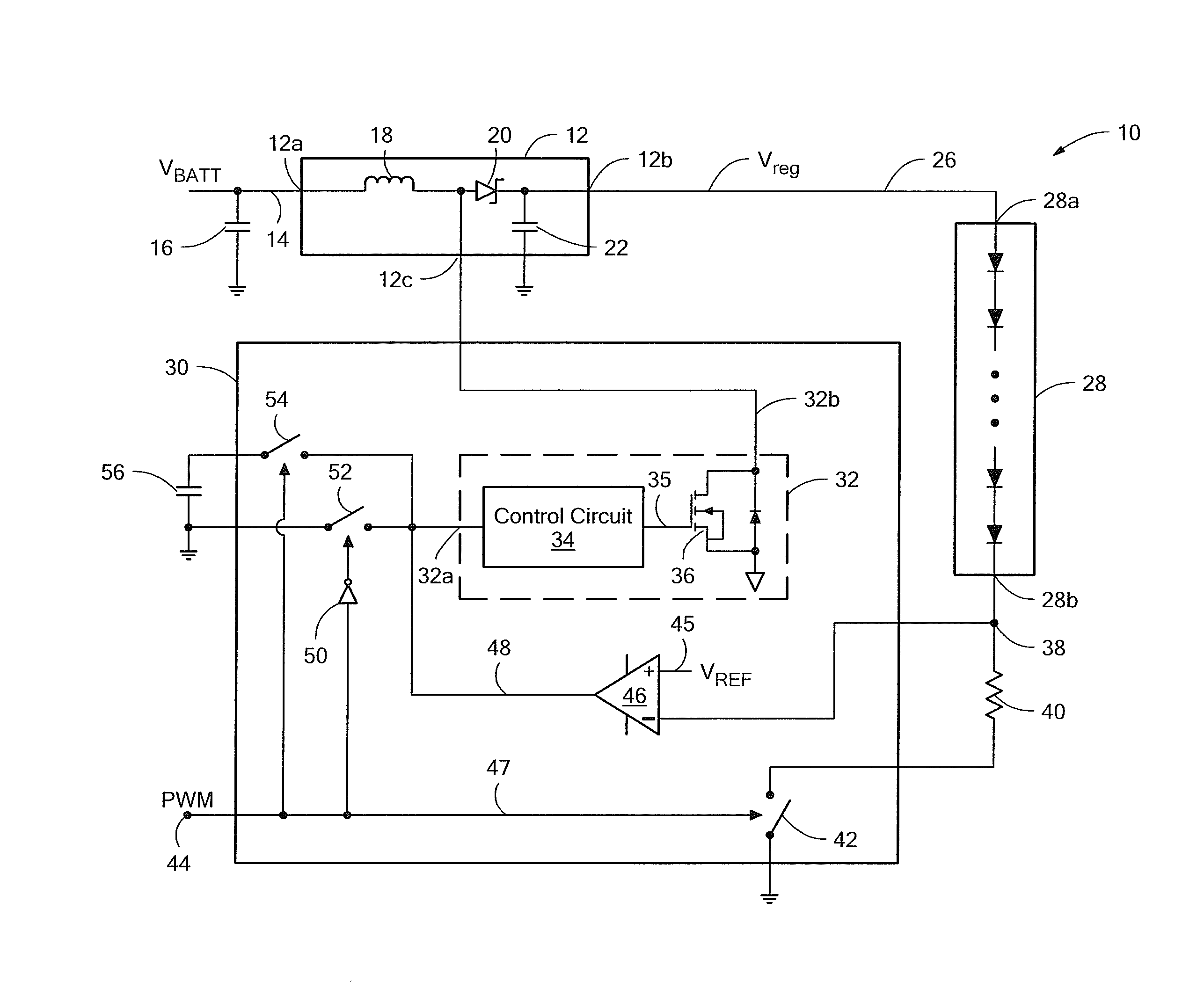
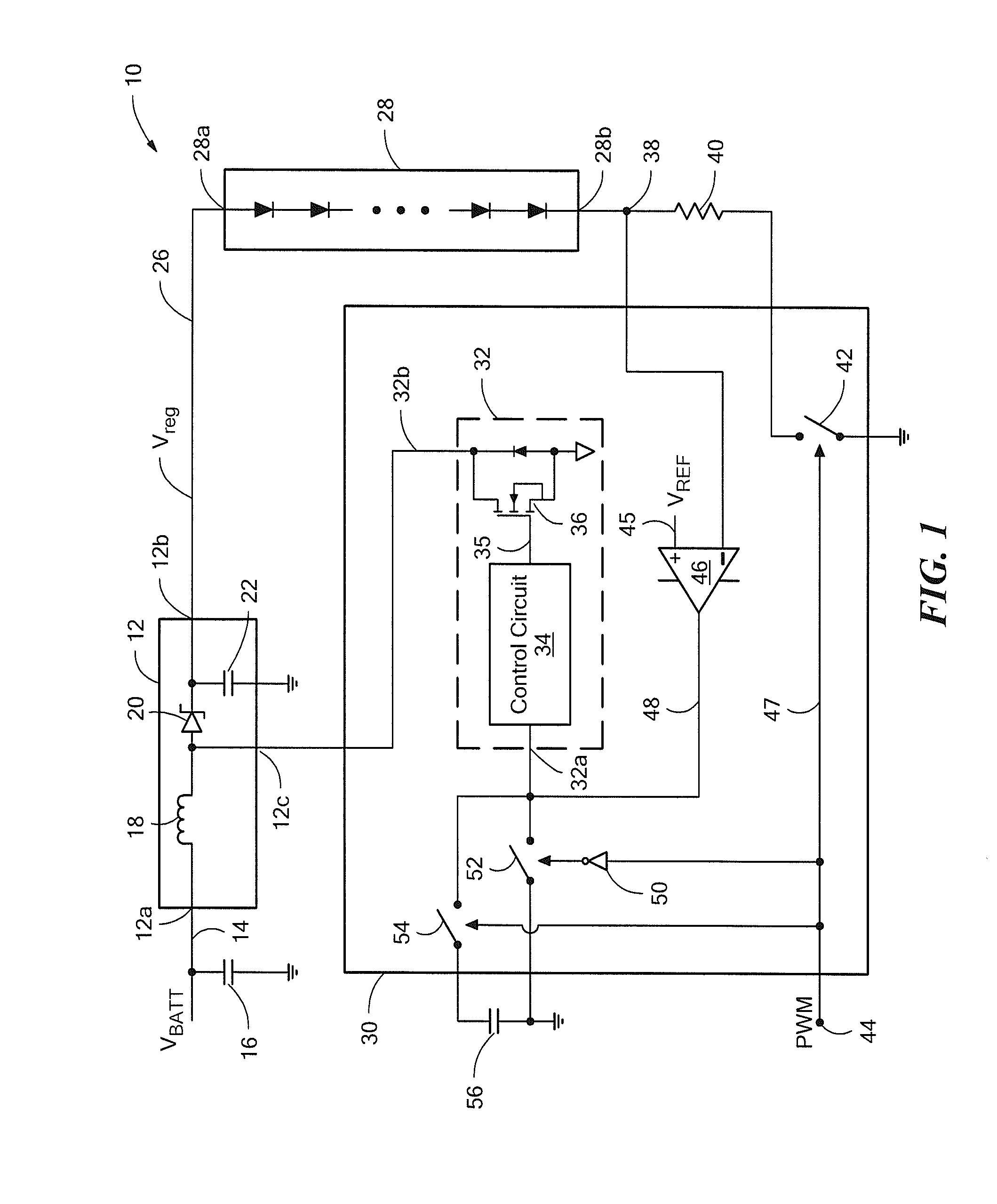
[0016]Referring to FIG. 1, an electronic circuit 10 for driving an LED load 28 with a controllable voltage converter 12 is shown. The voltage converter 12 has an input node 12a at which an input voltage 14, VBATT, is received, an output node 12b coupled to the LED load 28, and a control node 12c. In the illustrated embodiment, the controllable voltage converter 12 is a switching regulator and more particularly, is a boost switching regulator that provides a regulated output voltage 26, Vreg, at output node 12b that is greater than the input voltage 14. While a particular circuit topology of boost switching regulator is shown, it will be understood that a boost switching regulator can be formed in a variety of circuit configurations. It will be further understood that the controllable converter may take various conventional forms, such as a Buck converter, a Buck-boost converter, a charge pump, etc.

[0017]The LED load 28 comprises a string of series connected LEDs, as may be used in a...


PUM


Abstract

A circuit for driving an LED load with a controllable converter includes a control circuit configured to turn off the converter in response to a PWM signal having a first level and to turn on the converter in response to the PWM signal having a second level. A load disconnect switch coupled in series with the LED load is also controlled by the PWM signal so that the load disconnect switch is opened when the PWM signal turns off the converter to thereby open the load current path.

Description

FIELD OF THE INVENTION[0001]This invention relates generally to electronic circuits and, more particularly, to electronic circuits used to drive a light emitting diode (LED) load.BACKGROUND OF THE INVENTION[0002]Electronic driver circuits for driving an LED load often include a controllable DC-DC converter for providing a controlled current to the load. When the load contains multiple parallel strings of LEDs, the driver circuit often requires complex current regulator circuits to generate identical currents through each LED string. Generating identical LED currents is complicated by the fact that the forward voltage of the LED strings can differ.[0003]The need for complex current regulator circuits is eliminated in driver circuits that drive only a single LED string. In this case, the DC-DC converter can provide a controlled current to the LED string based on a simple feedback arrangement, such as sensing the voltage across a sense resistor coupled in series with the load.[0004]An ...

Claims


Application Information

Patent Timeline
Patent Type & Authority Applications(United States)
IPC IPC(8): H05B37/02H05B44/00
CPCH05B33/0851H05B33/0818H05B45/327H05B45/38H05B45/10H05B45/37H05B45/3725H05B31/50
Inventor SZCZESZYNSKI, GREGORY
Owner ALLEGRO MICROSYSTEMS INC
Why Eureka
Try Eureka