Switched-mode power supply

a power supply and switch-mode technology, applied in the direction of dc-dc conversion, power conversion systems, instruments, etc., can solve the problems of line regulation (rate of output voltage fluctuation with respect to input voltage fluctuation) degrade, and the protection circuit fails to function properly

Active Publication Date: 2012-11-01
MITSUMI ELECTRIC CO LTD
View PDF5 Cites 32 Cited by
  • Summary
  • Abstract
  • Description
  • Claims
  • Application Information

AI Technical Summary

Benefits of technology

[0013]In view of the above problems, the object of the present invention is to provide a technique to install a ripple injection function in a control circui

Problems solved by technology

Therefore, when a ripple component is to be injected into the feedback voltage of the output as in the ripple injection circuit of Japanese Examined Patent No. 4610588, there is a possibility

Method used


Image

  • Switched-mode power supply
  • Switched-mode power supply
  • Switched-mode power supply

Examples


first embodiment

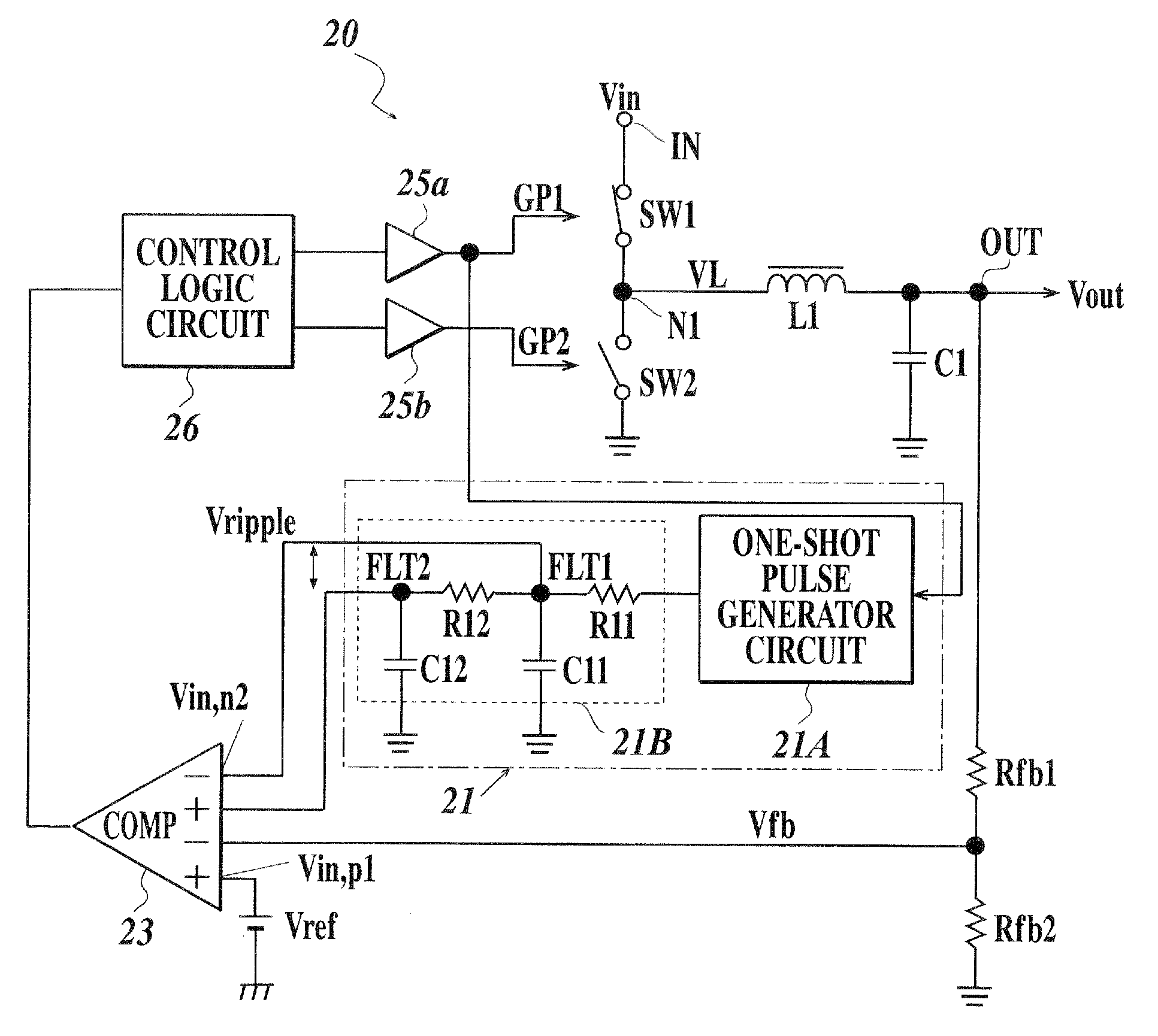
[0030]In the first embodiment, the pseudo ripple generator circuit 21 includes a one-shot pulse generator circuit 21A and a filter circuit 21B. The one-shot pulse generator circuit 21A generates a fixed pulse having a predetermined pulse width upon receiving the drive pulse GP1. The filter circuit 21B consists of resistors and capacitors for integrating the fixed pulse generated by the one-shot pulse generator circuit 21A. The one-shot pulse generator circuit 21A includes a delay circuit which delays the input signal for a predetermined pulse width and an exclusive OR gate or RS flip-flop which receives the signal which is delayed in the delay circuit and the input signal, for example. Here, the filter circuit 21B can be called otherwise as an integrating circuit which integrates the input pulse.

[0031]The switching control circuit 20 of this embodiment includes a comparator 23, a control logic circuit 26 and driver circuits 25a, 25b. The comparator 23 receives feedback voltage Vfb, ...

second embodiment

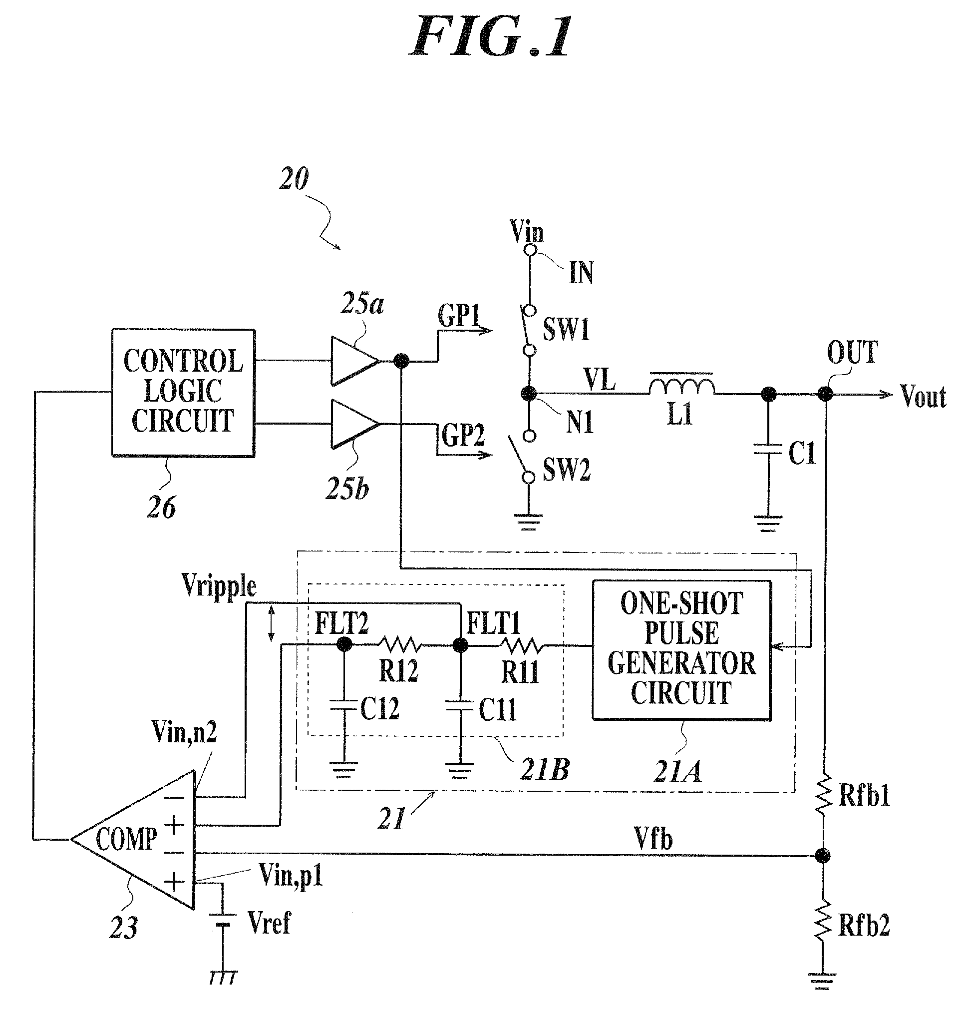
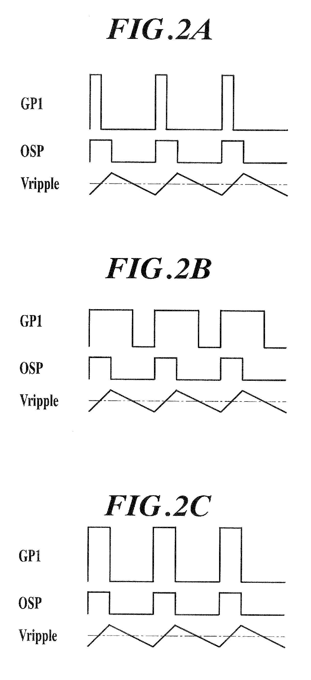
[0042]In the pseudo ripple generator circuit 21 of the second embodiment, as shown in FIGS. 4A to 4C, cycle of the one-shot pulse OSP to be output from the one-shot pulse generator circuit 21A matches the switching cycle (cycle of the drive pulse GP1) and the voltage Vramp to be output from the wave form generator circuit 21C forms a ramp wave form (sawtooth wave) that gradually increases only during the period when the one-shot pulse OSP is at low level. Therefore, even when the duty ratio of the drive pulse GP1 changes, the amplitude of the ramp wave form voltage Vramp which is generated as the pseudo ripple voltage is to be constant regardless of the duty ratio because the pulse width of the OSP is the same. Thereby, line regulation can be prevented from being degraded.

[0043]Moreover, in the case of the first embodiment shown in FIG. 1, although the line regulation is improved, there is a problem in the responsiveness at the time of load fluctuation. That is, in the DC-DC convert...


PUM


Abstract

Disclosed is a switched-mode power supply including an inductor which is connected between a voltage input terminal to which a DC voltage is input and an output terminal to which a load is connected, a driver switching element which intermittently feeds a current to the inductor and a control circuit which generates a control pulse according to a feedback voltage from output side and controls on/off of the driver switching element. The control circuit includes a voltage comparison circuit which compares the feedback voltage to a predetermined voltage and a pseudo ripple generator circuit which generates a pseudo ripple voltage having a predetermined amplitude, and the control circuit injects a ripple component in a transmission path of the feedback voltage based on the pseudo ripple voltage generated by the pseudo ripple generator circuit.

Description

CROSS-REFERENCE TO RELATED APPLICATIONS[0001]This application is based upon and claims the benefit of priority under 35 USC 119 of Japanese Patent Application NO. 2011-100913 filed on Apr. 28, 2011, the entire disclosure of which, including the description, claims, drawings, and abstracts, is incorporated herein by reference in its entirety.BACKGROUND OF THE INVENTION[0002]1. Field of the Invention[0003]The present invention relates to a DC-DC converter which transforms DC voltage based on the switching regulator system, and in particular to a switched-mode power supply having a ripple injection function.[0004]2. Description of Related Art[0005]DC-DC converter based on the switching regulator system has been known as a circuit which transforms DC input voltage into a DC voltage of different level. This sort of DC-DC converter includes a driver switching element, a rectifier element and a control circuit. The driver switching element applies DC voltage, received from a DC power suppl...

Claims


Application Information

Patent Timeline
IPC IPC(8): G05F1/46
CPCH02M3/156H02M1/14
Inventor NAKASHIMA, HEISUKE
Owner MITSUMI ELECTRIC CO LTD
Why Eureka
Try Eureka