Vehicle lamp generating superimposed light spots

a technology of superimposed light and vehicle lamps, which is applied in vehicle interior lighting, transportation and packaging, lighting and heating apparatus, etc., can solve the problems of limiting the anti-dazzling effect in said marginal area and the mechanical effort required to adjust the micro-mirrors, and achieves improved anti-dazzling effect, high beam distribution arrangement, and high beam function

Inactive Publication Date: 2012-11-01
HELLA KG HUECK & CO
View PDF13 Cites 4 Cited by
  • Summary
  • Abstract
  • Description
  • Claims
  • Application Information

AI Technical Summary

Benefits of technology

[0010]The special advantage of the invention is that defined reproduction properties can be realized by assigning separate optical elements to a plurality of LED light sources, so that a defined anti-dazzling area can be created in a high beam distribution arrangement. The fact that a plurality of light spots with two opposed vertical light / dark boundaries can be reproduced on a test screen makes it possible to set an anti-dazzling area with different widths by activating individual or a plurality of LED light sources. Depending on the actual position of the road user within the traffic area in front of the illumination device, it is therefore possible to achieve an improved anti-dazzling effect. The basic idea of the invention is to depict an extensive LED light source with two vertical sharp light / dark boundaries, so that certain anti-dazzling areas depending on the traffic situation can be activated in the high beam distribution arrangement and hence an approaching road user cannot be dazzled. The depiction of the LED light sources with two relatively sharp vertical light / dark boundaries each allows the generation of a plurality of switchable anti-dazzling areas.
[0011]According to a preferred embodiment of the invention, the right side of the first light spot and the left side of the second light spot have a non-vertical light-dark boundary or a fuzzy light / dark boundary, respectively, so that a combined light spot can be created by superimposing the two light spots which has relatively sharp light / dark boundaries on the right and left side. This can ensure a dazzle-free high beam function, specifically by means of rigid, immobile photometric components, wherein different anti-dazzling areas of the high beam distribution arrangement can be created by turning the LED light sources on and / or off.
[0012]According to an upgrade of the invention, the optical elements are each designed as reflector sections, wherein two reflector sections of a reflector with different orientations are preferably assigned to one LED light source. Advantageously, the reflector sections can be oriented in such a way that in each case they only need to depict a single sharp vertical light / dark boundary.
[0013]According to an upgrade of the invention, a plurality of LED light sources is combined to an LED lamp field (array), so that a homogeneous light distribution arrangement is generated when all LED light sources of the same LED lamp field are turned on.
[0014]According to a preferred embodiment of the invention, the optical element is designed or assigned to the LED light source in such a way that a rectangular or square light spot is depicted on a test screen when the LED light source is activated. As a result, the high beam distribution arrangement is composed of a plurality of said rectangular or square light spots, wherein corresponding vertical light / dark boundaries are depicted through the vertical edges of the light spots, by means of which anti-dazzling areas with a constant or variable width (in horizontal direction) can be created. Consequently, the anti-dazzling area can be set variably depending on the object within the traffic area to be anti-dazzled.
[0015]According to an upgrade of the invention, the combined light spots for the generation of the high beam distribution arrangement are arranged side-by-side in horizontal direction. Because the high beam distribution arrangement is created with a plurality of combined light spots, which comprise a sharp light / dark boundary each on the left and right side, the anti-dazzling area has a relatively high illuminance gradient both on the right as well as the left side.

Problems solved by technology

The disadvantage of the disclosed illumination device is that the mechanical effort required to adjust the micromirrors is relatively high.
However, reproduction errors in a marginal area of the light distribution arrangement are generated because of the relatively wide dimension of the optical unit designed as a lens, thus limiting the anti-dazzling effect in said marginal area.

Method used


Image

  • Vehicle lamp generating superimposed light spots
  • Vehicle lamp generating superimposed light spots
  • Vehicle lamp generating superimposed light spots

Examples


Embodiment Construction

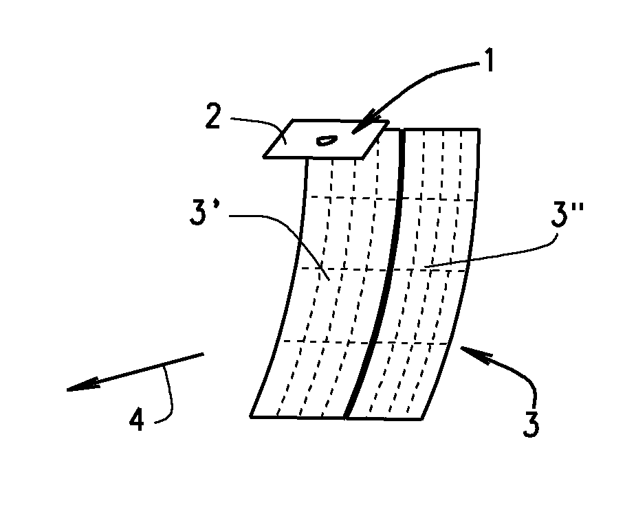
[0025]An illumination device according to the invention is used as headlights to generate a dazzle-free high beam function in a motor vehicle. The purpose of said headlights is to be able to generate a dynamic light function (Advanced Front lighting System, AFS), which allows the driving condition-related illumination of the road or the traffic area. For this purpose, LED light sources 1 of the headlights are turned on or off or dimmed (their brightness varied) by means of a control mechanism which is not illustrated. The control mechanism is connected with a sensor assembly on the input side which is designed to detect approaching road users and / or road users (objects) traveling in front. Depending on the sensor data provided by the sensor assembly, the LED light sources 1 of the illumination device are activated by a control mechanism, i.e. turned on or off or dimmed.

[0026]In the present exemplary embodiment, the LED light sources 1 designed as LED chips are combined to an LED lam...


PUM


Abstract

Illumination device for a dazzle-free high beam function with a plurality of LED light sources and an optical unit, with a sensor appliance to detect approaching road users and/or road users travelling in front, with a control mechanism which activates the LED light sources by means of dimming or turning them on and off depending on the sensor data supplied by the sensor assembly in such a way that an anti-dazzling area of the high beam function corresponding to the approaching road user and/or the road user travelling in front is created to prevent the road user from being dazzled, wherein at least the optical unit assigned to the high beam function includes optical elements assigned to the same LED light source, thereby producing least two light spots for every LED light source with the capability to superimpose the light spots on each other to create a combined light spot.

Description

RELATED APPLICATIONS[0001]This application claims priority and benefit of German Application No. 10 2011 001 865.4, filed on Apr. 7, 2011, all of which is incorporated herein by reference.BACKGROUND OF THE INVENTION[0002]1. Field of the Invention[0003]Illumination device for the generation of a dazzle-free high beam function with a plurality of LED light sources and an optical unit to create a high beam function, with a sensor assembly to detect approaching road users and / or road users travelling in front, with a control mechanism which activates the LED light sources by means of dimming or turning them on and off depending on the sensor data supplied by the sensor assembly in such a way that an anti-dazzling area of the high beam function corresponding to the approaching road user and / or the road user travelling in front is created to prevent the road user from being dazzled.[0004]2. Related Art[0005]An illumination device with an LED light source and an optical unit assigned to it...

Claims


Application Information

Patent Timeline
Patent Type & Authority Applications(United States)
IPC IPC(8): B60Q1/14
CPCF21S48/1159F21S48/1335F21S48/1747B60Q1/08B60Q1/085B60Q2300/45F21V7/00F21V7/10F21V23/04B60Q2300/054B60Q1/143F21S41/323F21S41/663F21S41/148
Inventor KLIEBISCH, DIRK
Owner HELLA KG HUECK & CO
Why Eureka
Try Eureka