Optical Multilayer Body

a multi-layer body and optical technology, applied in the field of optical laminates, can solve the problems of difficult to achieve the effect of anti-dazzling laminate per se, narrow and large curve of concave shape, and difficulty in achieving the effect of anti-dazzling laminates, etc., to achieve excellent anti-glare properties, excellent anti-glare properties, contrast, and letter blurring

Active Publication Date: 2009-03-05
DAI NIPPON PRINTING CO LTD
View PDF5 Cites 19 Cited by
  • Summary
  • Abstract
  • Description
  • Claims
  • Application Information

AI Technical Summary

Benefits of technology

[0018]The optical laminate according to the present invention can realize excellent anti-dazzling properties and black color reproduction having glossy black feeling, can realize a high level of sharpness and excellent anti-glare property, contrast, and letter blurring preventive property, and can be used in various displays. In particular, according to the optical laminate of the present invention, black color gradation rendering (glossy black color reproduction), which could not have been realized by the conventional anti-dazzling laminate without difficulties, can be significantly improved. More specifically, it is possible to provide an optical laminate which, in an image in movie display, can render gradation substantially comparable with a conventional display comprising a laminate, the laminate comprising a clear hard coat layer free from any concavoconvex shape and an antireflection layer provided on the clear hard coat layer and, at the same time, can realize a good sharpness of the contour of letters and can prevent scintillation. In a preferred embodiment of the present invention, the pro

Problems solved by technology

Accordingly, a concavoconvex shape having a broad and large curve has been regarded as unsuitable for meeting a demand for higher definition in the anti-dazzling laminate having the above construction and thus have not been adopted.
Regarding this technique, however, it has often been pointed out that, for example, external light is reflected from the display surface resulting in such a phenomenon that, for example, the image display surface is seen white (whitening), or lowered contrast.
When the light transmitted through the backside of backlight within a display is transmitted through the concavoconvex shape face of the anti-dazzling laminate formed on the outermost surface of the panel, however, the concavoconvex shape functions as fine lenses which disturb the displayed pixels and the like, that is, “glare” is likely to occur.
This unfavorable phenomenon makes it difficult to attain the effect of the anti-dazzling laminate per se.
On the other hand, in the anti-da

Method used


Image

  • Optical Multilayer Body
  • Optical Multilayer Body
  • Optical Multilayer Body

Examples


example 1

Formation of Anti-Dazzling Layer

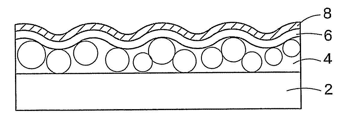
[0285]An 80 μm-thick triacetylcellulose film (TD80U, manufactured by Fuji Photo Film Co., Ltd.) was provided. Composition 1 for an anti-dazzling layer was coated onto the film with a wire-wound rod for coating (Mayer's bar), and the coated film was heat dried in an oven of 70° C. for one min to evaporate the solvent component. Thereafter, under nitrogen purge (oxygen concentration: not more than 200 ppm), ultraviolet light was applied at an exposure of 30 mJ for half curing to cure the coating film. Thus, a 5 μm-thick anti-dazzling hardcoat layer was formed. The light transparent fine particles were monodisperse acrylic beads having a particle diameter of 5.0 μm.

[0286]Formation of Surface Modifying Layer

[0287]Composition 1 for a surface modifying layer was coated onto the anti-dazzling layer with a wire-wound rod for coating (Mayer's bar), and the coating was heat dried in an oven of 70° C. for one min to evaporate the solvent component. Thereafter, u...

example 2

[0288]An optical laminate (HG2) was produced in the same manner as in Example 1, except that composition 2 for an anti-dazzling layer was used. The light transparent fine particles in composition 2 for an anti-dazzling layer were monodisperse acrylic beads having a particle diameter of 9.5 μm, and the surface modifying layer had a thickness of 4.0 μm.

example 3

[0289]An optical laminate (HG3) was produced in the same manner as in Example 1, except that composition 3 for an anti-dazzling layer was used. The light transparent fine particles in a coating composition for anti-dazzling layer formation were monodisperse acrylic beads having a particle diameter of 13.5 μm.


PUM

PropertyMeasurementUnit
Angleaaaaaaaaaa
Angleaaaaaaaaaa
Lengthaaaaaaaaaa

Abstract

The present invention provides an anti-dazzling laminate which has anti-dazzling properties and can realize excellent glare preventive properties and black color reproducibility (gradation rendering of black color at low brightness). The optical laminate comprises a light transparent base material and an anti-dazzling layer provided on the light transparent base material. The outermost surface of the anti-dazzling layer has a concavoconvex surface, and the average spacing S determined by calculation based on data obtained by measuring a roughness curve of a concacoconvex shape of the anti-dazzling layer is not less than 0.04 mm and not more than 0.30 mm.

Description

CROSS-REFERENCE TO RELATED APPLICATIONS[0001]This application is based upon and claims the benefit of priority from the prior Japanese Patent Applications No. 44231 / 2005 and No. 103061 / 2005 under the Paris Convention, and, thus, the entire contents thereof are incorporated herein by reference.BACKGROUND OF THE INVENTION[0002]1. Technical Field[0003]The present invention provides an optical laminate for use in displays such as CRTs and liquid crystal panels.[0004]2. Background Art[0005]The prevention of lowered contrast and lowered visibility caused by external light reflection or image reflection is required of image display devices, for example, cathode-ray tube display devices (CRTs), plasma displays (PDPs), electroluminescent displays (ELDs), or liquid crystal displays (LCDs). Accordingly, it is common practice to provide a reflection preventive laminate on the outermost surface of an image display device from the viewpoint of reducing image reflection or reflectance using the pr...

Claims


Application Information

Patent Timeline
IPC IPC(8): G02B1/10G02B5/30G02B5/02G02F1/1335
CPCG02B1/11G02B5/0226Y10T428/24669G02B5/0294G02F1/133502G02B5/0278B32B7/02
Inventor IWATA, YUKIMITSUMIKAMI, KOICHINISHIMURA, YOSHIHIROKODAMA, TAKASHI
Owner DAI NIPPON PRINTING CO LTD
Why Eureka
Try Eureka