
Optical coatings with plate-shaped particles and methods for forming the same

a technology of optical coatings and plate-shaped particles, applied in the direction of coatings, instruments, polarising elements, etc., can solve the problems of low throughput, difficult to achieve a substrate, and low manufacturing ra

Inactive Publication Date: 2015-03-10
GUARDIAN GLASS LLC
View PDF2 Cites 17 Cited by
  • Summary
  • Abstract
  • Description
  • Claims
  • Application Information

AI Technical Summary

Benefits of technology

The invention is about improving the performance of optical coatings to prevent glare on transparent surfaces. The method involves applying special coatings to the surface to reduce glare. This technology can be used to make ophthalmic lenses and other optical devices with improved clarity and reduced glare.

Problems solved by technology

It is difficult to achieve a substrate that simultaneously reduces gloss (i.e., specular reflection) and haze (i.e., diffuse transmittance) while relying on light scattering to obtain anti-glare properties.
Such methods are expensive, have low throughput (i.e., a low rate of manufacture), and lack of precise control with respect to surface texture, which results in a diffuse scattering coating with poor light transmittance or good light transmittance, but poor reduction of glare.
Additionally, coatings formed using the polymeric films often demonstrate poor abrasion resistance and cohesive strength, resulting in the coatings (and / or the substrate itself) being damaged when various forces are experienced.

Method used

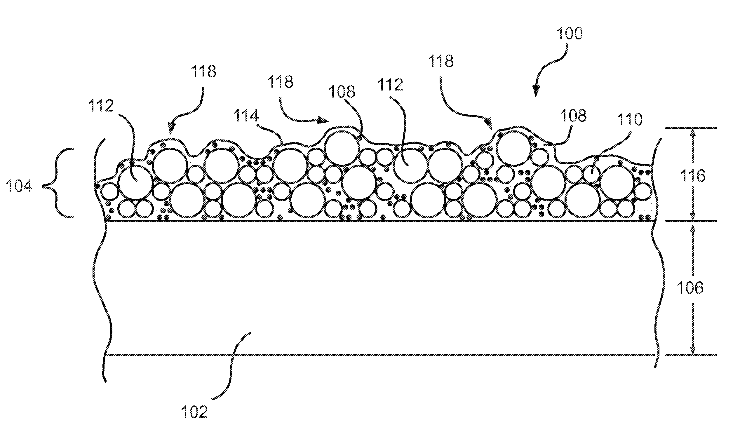
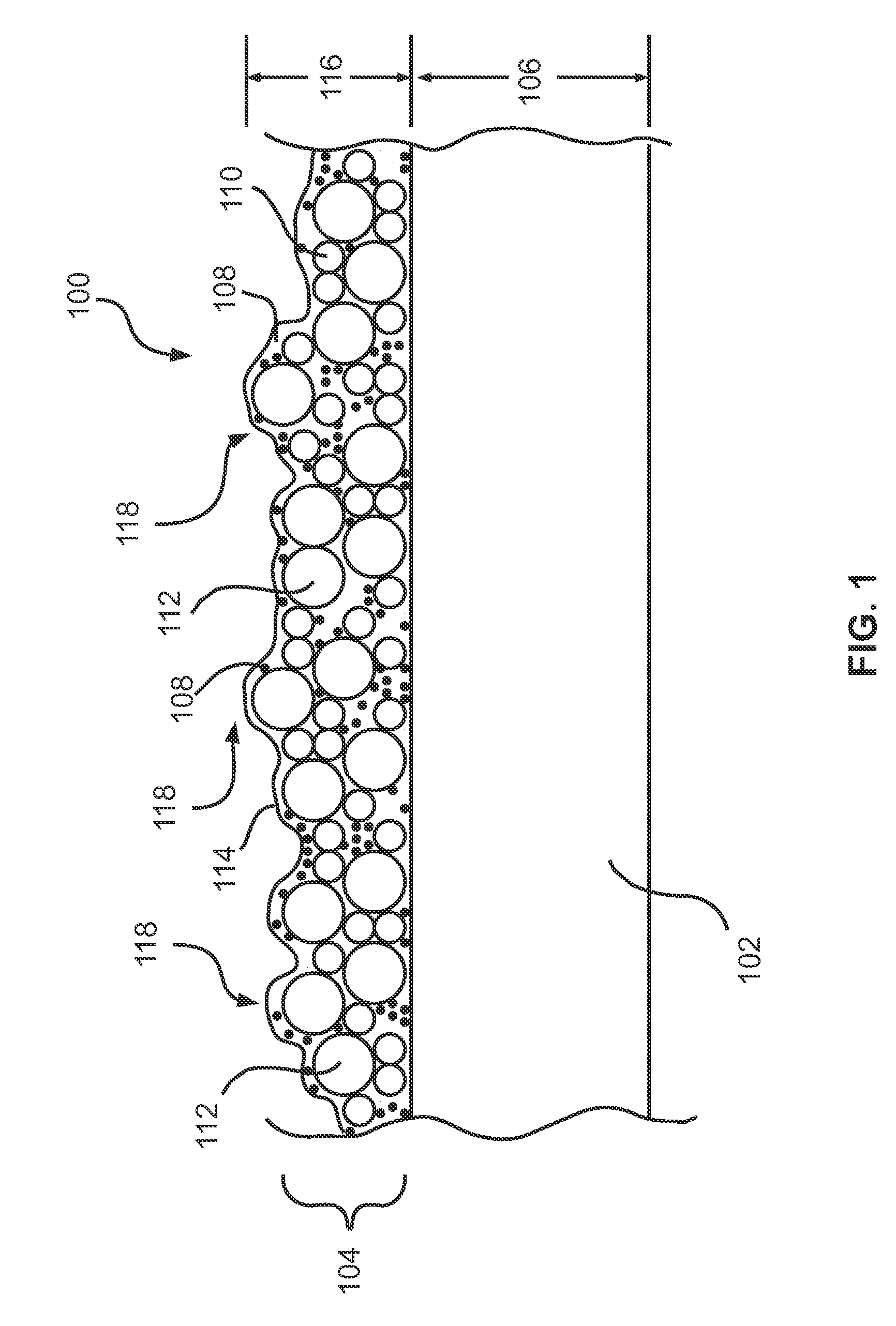
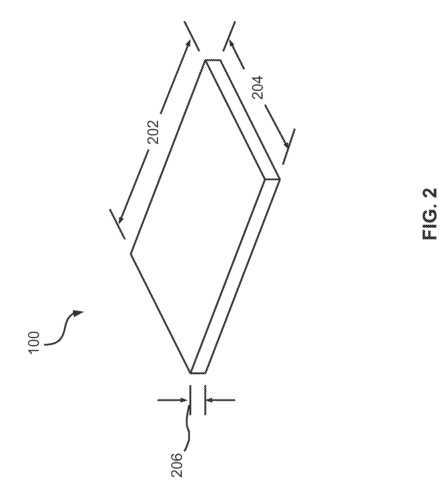

Image

  • Optical coatings with plate-shaped particles and methods for forming the same
  • Optical coatings with plate-shaped particles and methods for forming the same
  • Optical coatings with plate-shaped particles and methods for forming the same

Examples


Embodiment Construction

[0013]A detailed description of one or more embodiments is provided below along with accompanying figures. The detailed description is provided in connection with such embodiments, but is not limited to any particular example. The scope is limited only by the claims and numerous alternatives, modifications, and equivalents are encompassed. Numerous specific details are set forth in the following description in order to provide a thorough understanding. These details are provided for the purpose of example and the described techniques may be practiced according to the claims without some or all of these specific details. For the purpose of clarity, technical material that is known in the technical fields related to the embodiments has not been described in detail to avoid unnecessarily obscuring the description.

[0014]Embodiments described herein provide for optical coatings, and methods for forming optical coatings, that improve the anti-glare (and / or the anti-reflective) performance...


PUM

PropertyMeasurementUnit
thicknessaaaaaaaaaa
thicknessesaaaaaaaaaa
diameteraaaaaaaaaa

Abstract

Embodiments provided herein describe optical coatings, panels having optical coatings thereon, and methods for forming optical coatings and panels. A transparent substrate is provided. An optical coating is formed on the transparent substrate. The optical coating includes a plurality of plate-shaped silicon dioxide particles.

Description

[0001]The present invention relates to optical coatings. More particularly, this invention relates to optical coatings that improve, for example, the anti-glare performance of transparent substrates and methods for forming such optical coatings.BACKGROUND OF THE INVENTION[0002]Anti-glare coatings, and anti-glare panels in general, are desirable in many applications including, portrait glass, privacy glass, and display screen manufacturing. Such optical coatings scatter specular reflections into a wide viewing cone to diffuse glare and reflection. It is difficult to achieve a substrate that simultaneously reduces gloss (i.e., specular reflection) and haze (i.e., diffuse transmittance) while relying on light scattering to obtain anti-glare properties.[0003]Conventional methods of forming anti-glare panels include, for example, wet etching the surface of the substrate, using mechanical rollers with pre-defined textures on substrates to create a surface roughness, and applying thin, pol...

Claims


Application Information

Patent Timeline
Patent Type & Authority Patents(United States)
IPC IPC(8): G02B27/00G02B1/11
CPCG02B1/11G02B1/111G02B1/118G02B5/0242G02B5/0294G02B2207/101G02B2207/107G02B2207/109
Inventor KALYANKAR, NIKHILBLACKER, RICHARDJEWHURST, SCOTTMULLIGAN, JAMES
Owner GUARDIAN GLASS LLC
Learn More