
Spring tube melting machine for air suspension system

a technology of air suspension system and spring tube, which is applied in the direction of transportation and packaging, other domestic objects, hollow objects, etc., can solve the problems of uneven surface formation of air springs, inconvenience in disassembling the spring tube melting machine, and bad molding of spring tubes, etc., to prevent bad molding, easy replacement, and easy formation

Active Publication Date: 2012-11-01
SUNJIN PRECISION
View PDF9 Cites 0 Cited by
  • Summary
  • Abstract
  • Description
  • Claims
  • Application Information

AI Technical Summary

Benefits of technology

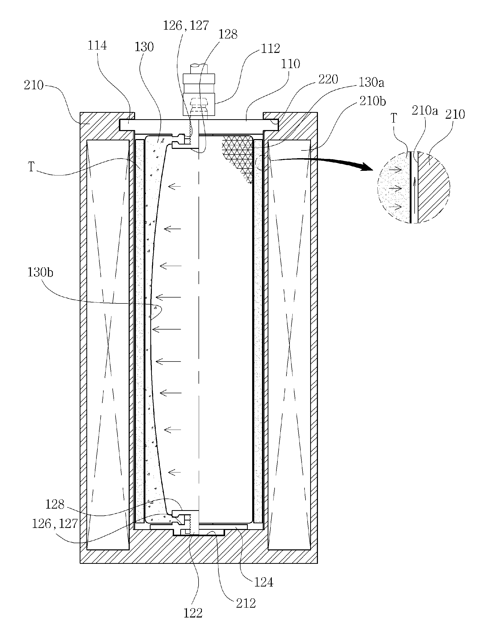
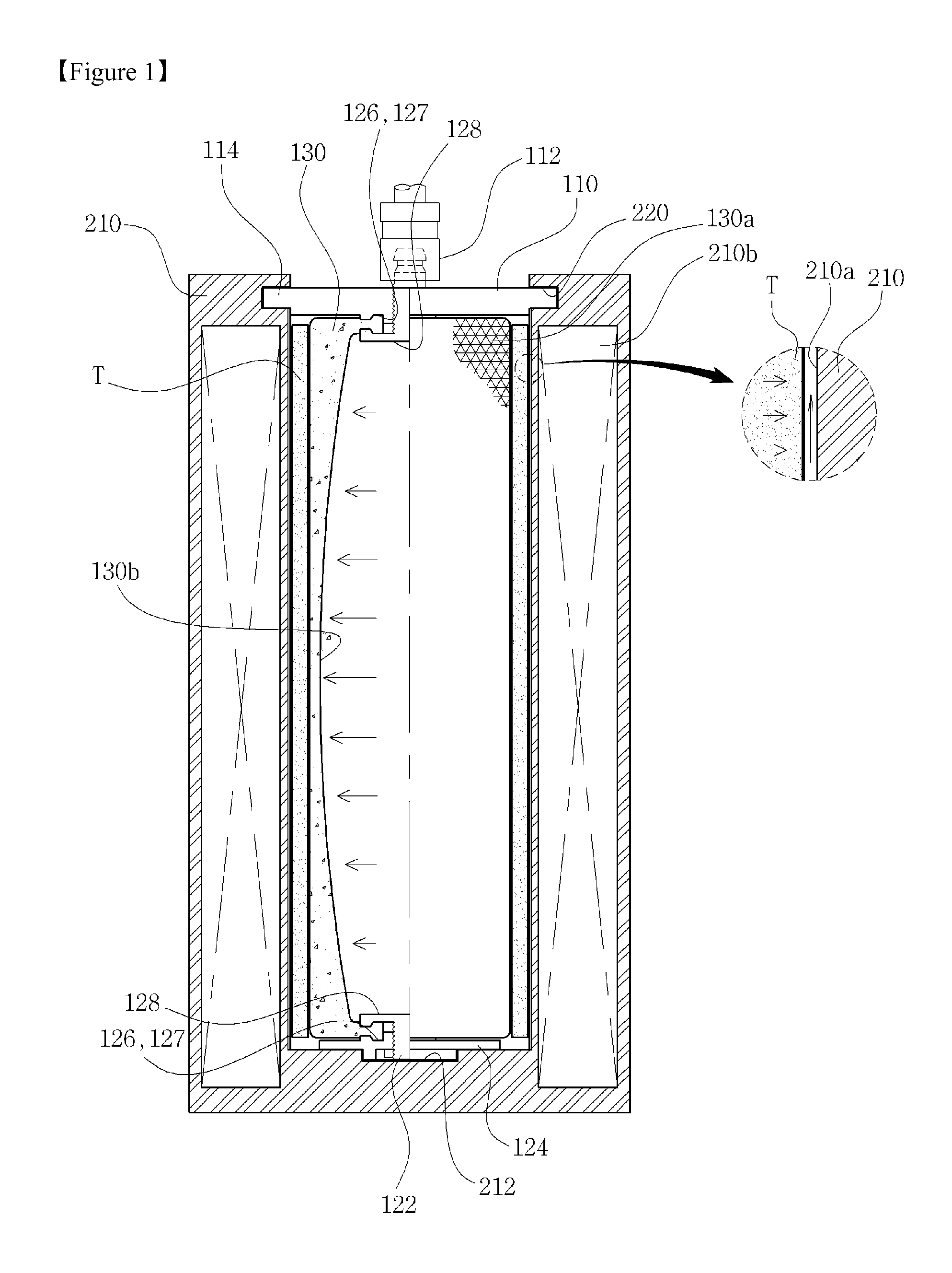
[0015]As described above, in the spring tube melting machine for the air suspension system according to the present invention, air remaining between the spring tube and the heating core is rapidly discharged out along the air discharge valleys because the expandable tube presses the spring tube while being gradually expanded from the central portion to both edge portions. Moreover, because pressure force is applied from the inside to the outside by the expansion force of the expandable tube, the spring tube melting machine can prevent bad molding due to overlap of the spring tubes, and especially, the expandable tube can be easily replaced during use because it is detachably mounted by the finish plate.
[0016]Furthermore, after the relief engraving portion is formed on the inner circumferential surface of the spring tube using the intaglio engraving portion formed on the expandable tube, when the spring tube is turned inside out, the relief engraving portion is formed on the outer circumferential surface of the spring tube, and hence, the relief engraving portion can be easily formed on the surface of the spring tube.

Problems solved by technology

The spring tube melting machines according to the prior arts are manufactured with the purpose of easily manufacturing spring tubes, but have many problems in use.
First, when the mandrill presses the air spring while performing expansion and contraction, the surface of the air spring is formed unevenly because remaining air between the mandrill and the air spring cannot be discharged rapidly.
Second, when the mandrill which is used as consumable goods is replaced with a new one, there is an inconvenience to completely disassemble the spring tube melting machine.
Third, in order to form pyramid-shaped relief engraving portions on the air spring, because intaglio engraving portions, which is difficult to do cutting work, must be formed on the surface of the cartridge, it requires expensive prices to manufacture the cartridge.

Method used


Image

  • Spring tube melting machine for air suspension system
  • Spring tube melting machine for air suspension system
  • Spring tube melting machine for air suspension system

Examples


Embodiment Construction

[0021]Reference will be now made in detail to the preferred embodiment of the present invention with reference to the attached drawings.

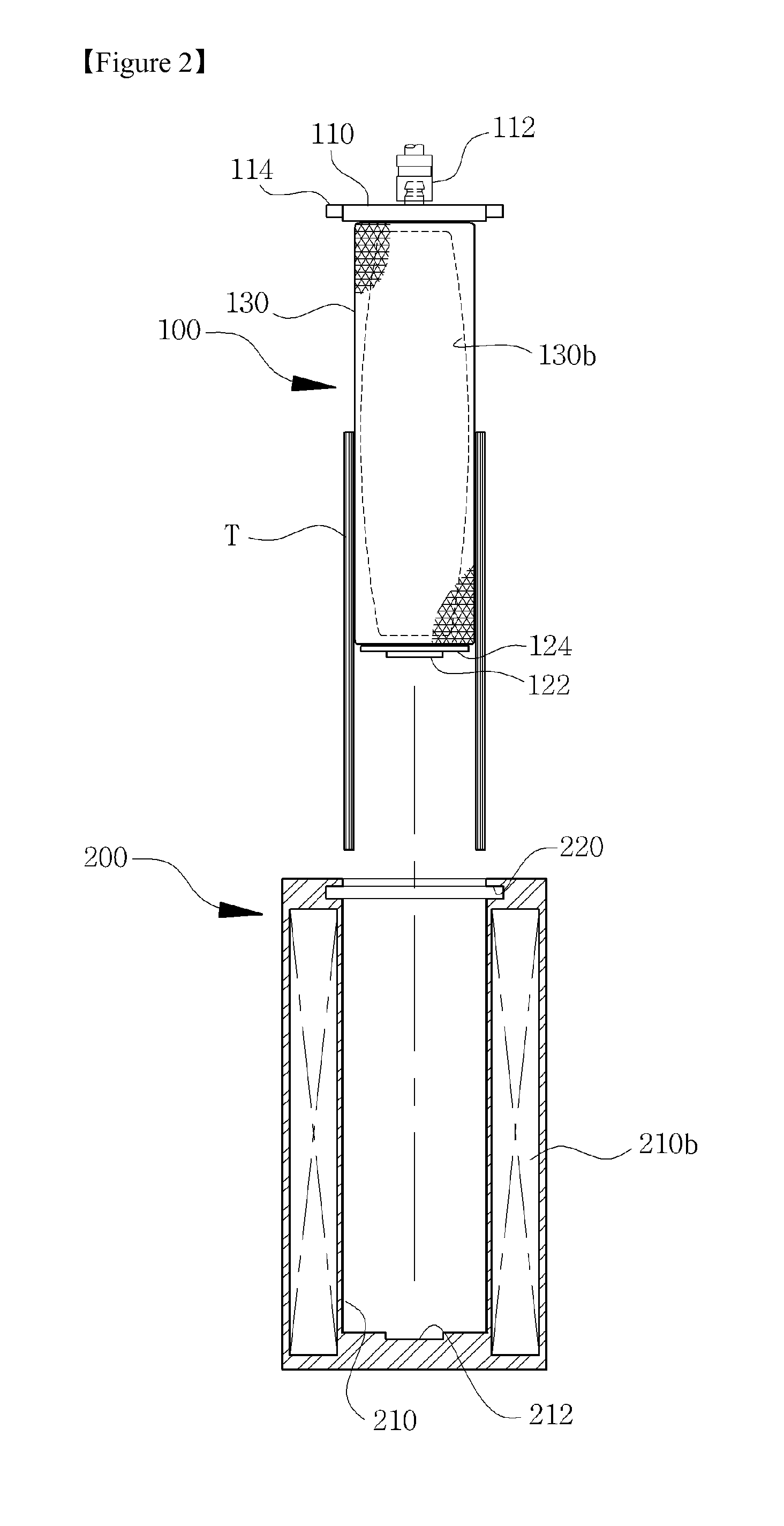
[0022]FIG. 1 is a configurative view showing a spring tube melting machine for an air suspension system according to the present invention, FIG. 2 is a configurative view showing an inner molding part and an outer molding part of the spring tube melting machine for the air suspension system, FIG. 3 is a configurative view showing a joining key and a joining key recess of the spring tube melting machine for the air suspension system, and FIG. 4 is a configurative view showing a state where the spring tube formed through the spring tube melting machine for the air suspension system is turned inside out.

[0023]The present invention relates to a spring tube melting machine for an air suspension system, and the spring tube melting machine for the air suspension system forms an integrated spring tube by compressing half-finished spring tubes at high temper...


PUM

PropertyMeasurementUnit
thicknessaaaaaaaaaa
temperatureaaaaaaaaaa
pressureaaaaaaaaaa

Abstract

Disclosed therein is a spring tube melting machine of an air suspension system. The spring tube melting machine includes an inner molding part (100) and an outer molding part (200), which can mold an integrated spring tube by compressing half-finished spring tube materials at high temperature in order prevent bad molding due to the remaining air and overlap of spring tube materials and simplify maintenance due to repeated use.

Description

TECHNICAL FIELD [0001]The present invention relates to a spring tube melting machine for an air suspension system, and more particularly, to a spring tube melting machine for an air suspension system, which can form an air spring tube by melting tube materials stacked up in multiple layers at high temperature.BACKGROUND ART [0002]In general, an air suspension system serves to reduce a damage of a car body and provide a comfortable ride to a passenger by connecting a car axle and the car body with each other by pneumatic pressure to thereby properly reduce vibration or shock transferred from the surface of the road during drive, so as to adjust a buffer power according to drive conditions and provide smoother feeling of drive by adjusting pneumatic pressure.[0003]Moreover, the air suspension system includes a spring tube mounted between a lower housing fixed to the car axle and an upper housing fixed to the car body. The spring tube performs a buffering action when compressed air is ...

Claims


Application Information

Patent Timeline
Patent Type & Authority Applications(United States)
IPC IPC(8): B29C49/64
CPCB29D22/023B60G2202/152B60G11/27B60G11/26F16F9/04
Inventor KIM, JONG HUN
Owner SUNJIN PRECISION
Learn More