
UHT System and Method for Heat Treating Temperature-Sensitive Food Products

a technology of food products and heat treatment, applied in the direction of heat exchanger types, indirect heat exchangers, lighting and heating apparatus, etc., can solve the problems of general and systematic increase of dwell time differences, and limitation of tube area allocation

Active Publication Date: 2012-11-01
GEA TDS
View PDF0 Cites 13 Cited by
  • Summary
  • Abstract
  • Description
  • Claims
  • Application Information

AI Technical Summary

Benefits of technology

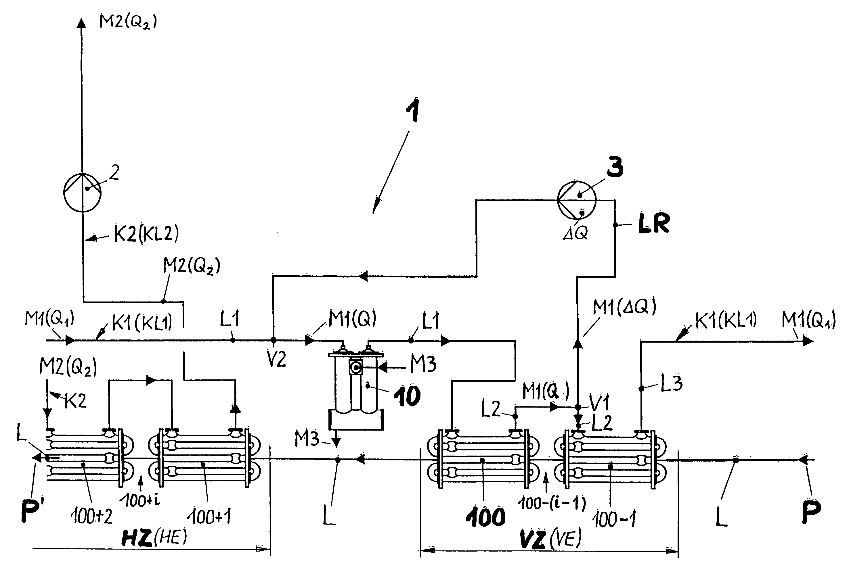
[0020]In order to perform this temperature adjustment promptly and efficiently, according to a second inventive basic idea it is provided that a return line branches off at a branch point from a second line section, which forms a further section of the continuing first circuit line and which conducts the first heating medium away from the first heat exchanger of the pre-heating zone. The return line opens into the first line section at a union point upstream of the trimming heater with respect to the flow direction of the first heating medium in the first line section. A second conveying device that conveys from the branch point to the union point is arranged in the return line, by which the conveying capacity in the area of the additionally heated first heating medium can be increased significantly. By doing so, the additionally heated first heating medium is promptly brought into the first heat exchanger of the pre-heating zone, and at the same time the heat transfer conditions on the side of the first heating medium are significantly improved there by the increase of the flow velocity. The improvement related to this is accompanied by an adequate improvement of the heat transfer conditions at the side of the food product, which is also proposed according to the present invention. This is achieved by a significant increase of the flow velocity in the inner tubes.
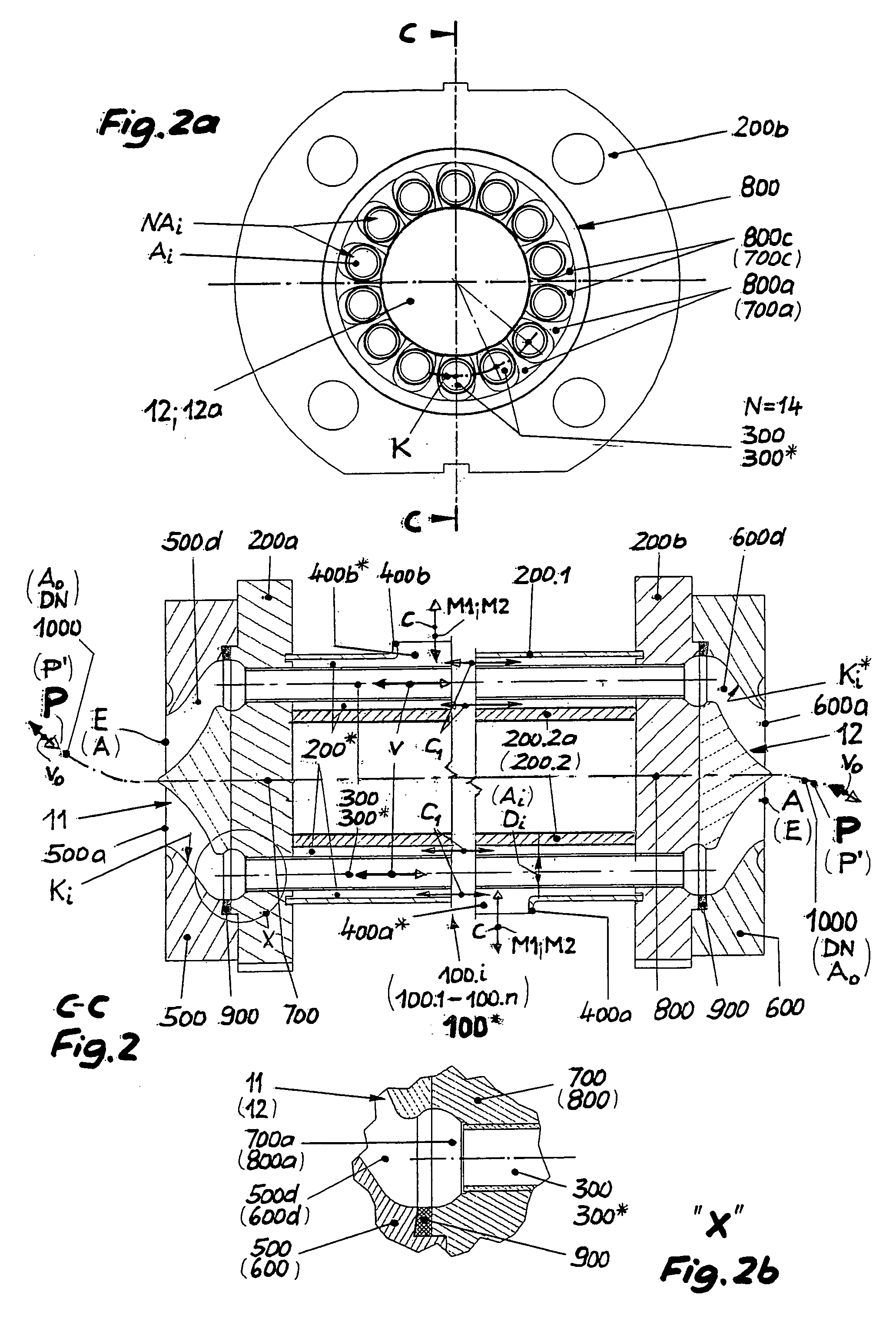
[0025]Congruent flow paths for the food product in the area of its branching and uniting partial amounts and in the flow region between the branch- and the union points for ensuring equal dwell times in the areas of the heat treatment of the food product are in principle ensured by the third inventive basic idea indicated above. Moreover, best possible prerequisites for the concrete realisation of congruent flow paths are created in that the inner tubes of the tube bundle are arranged in the maximum possible perimeter area of the tube support plate. This embodiment is preferably designed such that the gap width of the ring chamber is dimensioned as small as necessary for sufficient flow of heating medium, and the circle diameter on which the inner tubes are disposed is dimensioned as big as possible.
[0028]It has proven as advantageous to generate the velocity of approach in the annular chamber mentioned above at least in the first heat exchanger of the pre-heating zone, to which the additionally heated heating medium is supplied, from a volume flow which is approximately equal to a volume flow at the side of the second heating medium in the heat exchanger of the high-heating zone which joins the pre-heating zone.
[0043]The optimum heat transfer conditions at the side of the first heating medium created by the arrangement of the inner tubes in the shape of a circular ring on a single circle and in an outer channel designed as an annular chamber according to the present invention result to an all in all improved passage of heat to the food product flowing in the inner tubes, if, as provided by a further proposal, the heat transfer conditions in the area of the pre-heating comprised by the additional heating of the first heating medium are correspondingly adjusted at the side of the food product to the heat transfer conditions at the side of the first heating medium, namely by increasing the flow velocity in the inner tube.

Problems solved by technology

The allocation on the tube area is subject to a limitation insofar, because the centre of the tube support plate must remain free of one or even several inner tubes.
By this, the centre of the tube support plate is also available for arranging inner tubes there, through which however, the flow paths differ still more in the course of the branching and union of the flow than upon allocation of the tube support plate with free centre, and thus, even greater dwell time differences are created generally and systematically.

Method used


Image

  • UHT System and Method for Heat Treating Temperature-Sensitive Food Products
  • UHT System and Method for Heat Treating Temperature-Sensitive Food Products
  • UHT System and Method for Heat Treating Temperature-Sensitive Food Products

Examples


Embodiment Construction

[0054]While this invention may be embodied in many different forms, there are described in detail herein a specific preferred embodiment of the invention. This description is an exemplification of the principles of the invention and is not intended to limit the invention to the particular embodiment illustrated.

[0055]A heat-sensitive product P to be subjected to heat treatment, like a dessert or a dessert-like product, enters in the partial area of a UHT system 1 depicted in FIG. 1 into a pre-heating zone VZ via a product line L. The pre-heating zone VZ, in which the food product P experiences a pre-heating VE, is formed by a first heat exchanger 100 of the pre-heating zone and a second heat exchanger 100−1 of the pre-heating zone, which is arranged upstream of the former with respect to the flow direction of the food product P. Via a first circuit line K1, both are impinged by a regeneratively generated first heating medium M1, preferably water. The latter is conveyed in the first ...


PUM


Abstract

The invention relates to a UHT system for heat treating temperature-sensitive food products, in particular desserts or dessert-like products, comprising a pre-heating zone and a subsequent high-heating zone. The aim of the invention is to achieve accurate and fast temperature adjustment of the food product leaving the pre-heating zone to the temperature conditions at the inlet of the high-heating zone in a UHT system of the generic type, and at the same time, with an equal dwell time for all partial amounts of the food product, to ensure that the food product is treated in a particularly thermally gentle manner and to keep the mechanical loading of the food product as low as possible.

Description

CROSS-REFERENCE TO RELATED APPLICATIONS[0001]This is a national stage application of PCT / EP2010 / 007765, filed on Dec. 17, 2010, the entire contents of which are hereby incorporated by referenceSTATEMENT REGARDING FEDERALLY SPONSORED RESEARCH[0002]Not applicable.BACKGROUND OF THE INVENTION[0003]The present invention relates to a UHT system for heat treating temperature-sensitive food products, desserts or dessert-like products in particular, with a pre-heating zone which has at least one first heat exchanger, which is / are impinged by the food product to be heated via a product line on the one hand, and by a regeneratively generated first heating medium via a first circuit line on the other hand, with a high-heating zone joining the first heat exchanger upstream with respect to the flow direction of the food product and comprising at least one second heat exchanger which is / are impinged by the food product via the product line on the one hand, and by a second heating medium via a seco...

Claims


Application Information

Patent Timeline
Patent Type & Authority Applications(United States)
IPC IPC(8): F28D15/00A23L3/22
CPCA23L3/16F28F9/028F28D7/1669F28D7/10A23L3/22A23V2002/00
Inventor TACKE, LUDGERBUSCH, NORBERTZIMMERMANN, DEITRICHASSING, HUBERTSCHWENZOW, UWESCHLAG, BRIGITTE
Owner GEA TDS
Learn More