Latch mechanism for battery retention

a latch mechanism and battery technology, applied in the field of latch mechanism for battery retention, can solve the problems of battery pack powering the device becoming disengaged from the device, experienced paramedics cannot maintain adequate chest compression for more than a few minutes, and the patient is not often successful in sustaining or reviving the patien

Inactive Publication Date: 2012-11-01
ZOLL CIRCULATION
View PDF23 Cites 31 Cited by
  • Summary
  • Abstract
  • Description
  • Claims
  • Application Information

AI Technical Summary

Benefits of technology

[0011]In a most general aspect, the invention provides a latch mechanism for ensuring the retention of a high-performance battery pack in a device to be powered by the battery pack. The latch mechanism is configured to engage with a portion of the device to be powered in a manner that will ensure retention of the battery within the device in the event the device is bumped, dropped, roughly handled, or otherwise submitted to a shock that might otherwise cause the battery to disengage from the powered device. In one aspect, the latch mechanism of the present invention may prevent inadvertent disengagement of the battery leading to cessation of operation of the powered device, which, depending on the circumstances surround the use of the device, could be damaging or harmful.

Problems solved by technology

However, even experienced paramedics cannot maintain adequate chest compressions for more than a few minutes.
Thus, CPR is not often successful at sustaining or reviving the patient.
For example, under such use the battery pack powering the device may become disengaged from the device when it is dropped or jostled.
Such disengagement will require, at the least, re-insertion of the battery in the battery compartment, and may even cause damage to the battery requiring replacement of the battery.
Even if the battery is not completely disengaged, the battery may become loose in the battery compartment.
This may cause a disconnection of the battery during use which will stop operation of the mechanical compression device, and require quick troubleshooting by the user of the device to determine why the device is no longer operating.
Such a loose engagement may also increase the resistance of the electrical connection between the battery and the device.
This increased resistance may lead to a decreased battery capacity, requiring compressions to be halted for replacement of the battery in a shorter than expected time.

Method used


Image

  • Latch mechanism for battery retention
  • Latch mechanism for battery retention
  • Latch mechanism for battery retention

Examples


Embodiment Construction

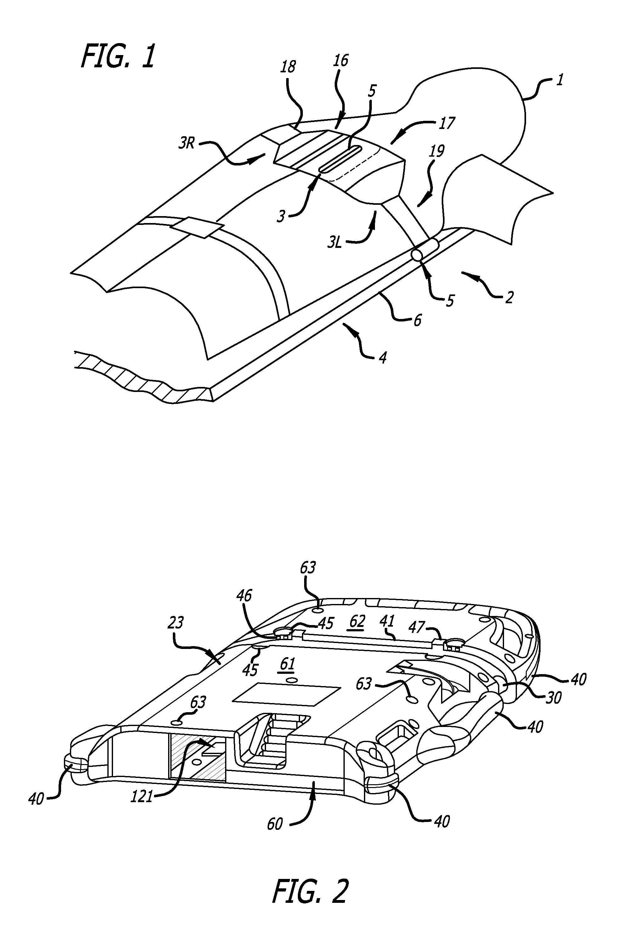
[0029]The various embodiments of the present invention are directed to providing a rechargeable battery for powering mobile equipment, particularly medical devices. The embodiments of the invention are particularly advantageous when the battery is required to provide a large amount of current over a predictable period of time. Moreover, the embodiments of the invention include a battery management system that controls all aspects of the operation of the battery, and also includes a memory in which events related to the battery that occur during the battery's lifetime are stored. Moreover, embodiments of the battery management system include the capability of accommodating batteries using different battery chemistries, and are also capable of being updated through a communication port.

[0030]While the various embodiments of the invention are described with reference to a mechanical compressions device, those skilled in the art will immediately appreciate that those embodiments are not...


PUM

PropertyMeasurementUnit
mean chest circumferenceaaaaaaaaaa
depthaaaaaaaaaa

Abstract

A latch mechanism for retaining a battery within a battery compartment is described.

Description

CROSS-REFERENCES TO RELATED APPLICATIONS[0001]This application claims the benefit of priority to U.S. Provisional Application No. 61 / 522,207, filed Aug. 10, 2011, and U.S. Provisional Application No. 61 / 480,286, filed Apr. 28, 2011, the entireties of which are hereby incorporated herein by reference.[0002]This application is related to U.S. application Ser. No. ______, entitled “Battery Management System For Control of Lithium Power Cells,” filed ______; U.S. application Ser. No. ______, entitled “Battery Management System With MOSFET Boost System,” filed ______; U.S. application Ser. No. ______, entitled “System and Method For Automatic Detection Of Battery Insertion,” filed ______; U.S. application Ser. No. ______, entitled “System and Method For Tracking And Archiving Battery Performance Data,” filed ______; U.S. application Ser. No. ______, entitled “Viral Distribution of Data, Operating Parameters and Software Using A Battery As A Carrier,” filed ______; the entireties of which...

Claims


Application Information

Patent Timeline
Patent Type & Authority Applications(United States)
IPC IPC(8): H01M2/10
CPCH01M2/1055H01M2/1235A61H31/006H01M2220/30H01M10/4257H01M50/20H01M50/213H01M50/342Y02E60/10A61H2201/1207E05C1/02E05C1/08E05C1/14
Inventor PENDRY, CRAIG
Owner ZOLL CIRCULATION
Why Eureka
Try Eureka