Cable grommet for use with a raised floor

Active Publication Date: 2012-11-08
EATON INTELLIGENT POWER LIMITED
View PDF7 Cites 9 Cited by
  • Summary
  • Abstract
  • Description
  • Claims
  • Application Information

AI Technical Summary

Benefits of technology

[0004]The invention disclosed herein provides cable grommets for use with prior art raised-floor systems. In preferred embodiments, the cable grommets of the invention are configured to be mounted within a standard-s

Problems solved by technology

Unfortunately, these openings in the raised floor also allow cooling air to esc

Method used


Image

  • Cable grommet for use with a raised floor
  • Cable grommet for use with a raised floor
  • Cable grommet for use with a raised floor

Examples


Embodiment Construction

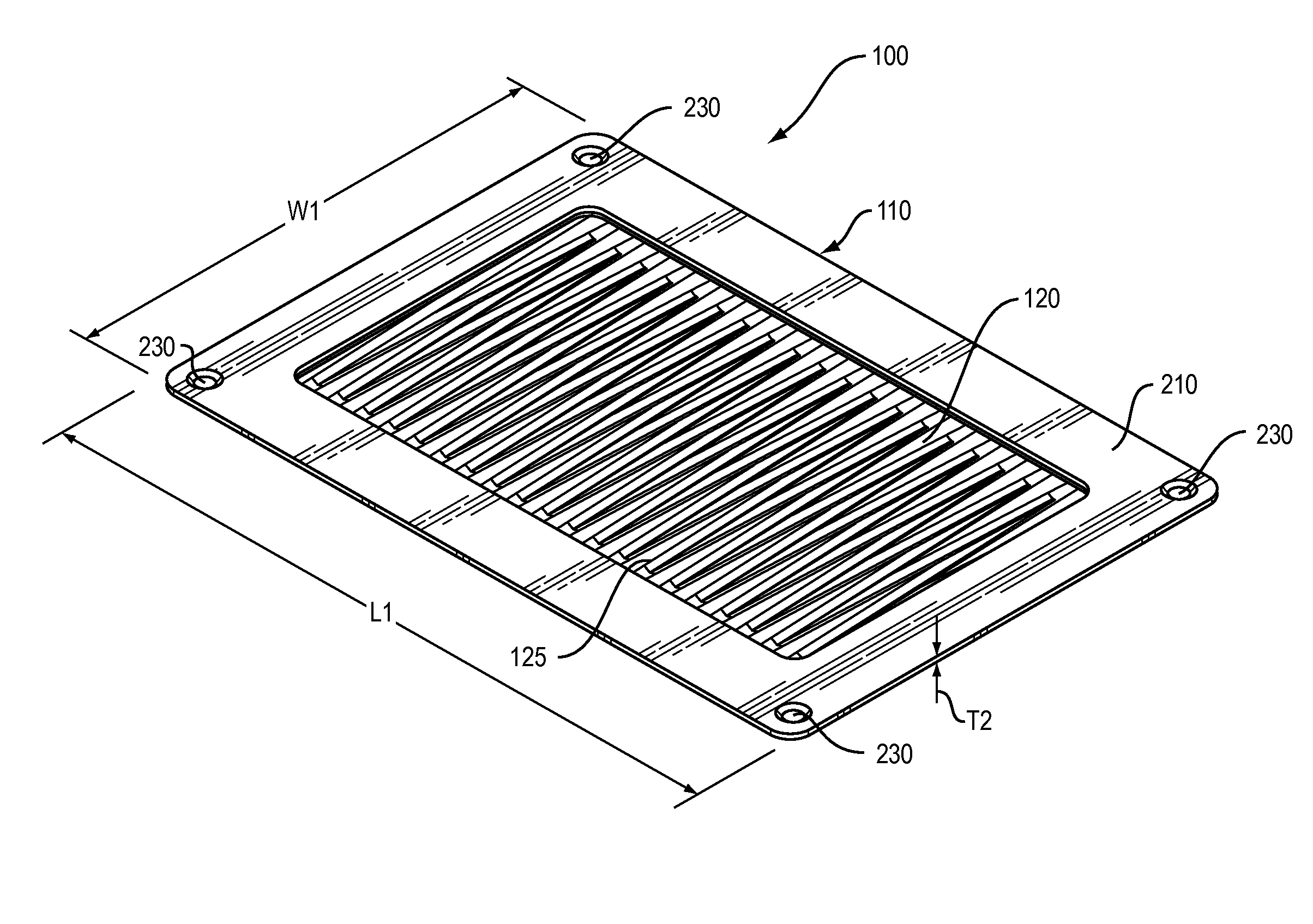
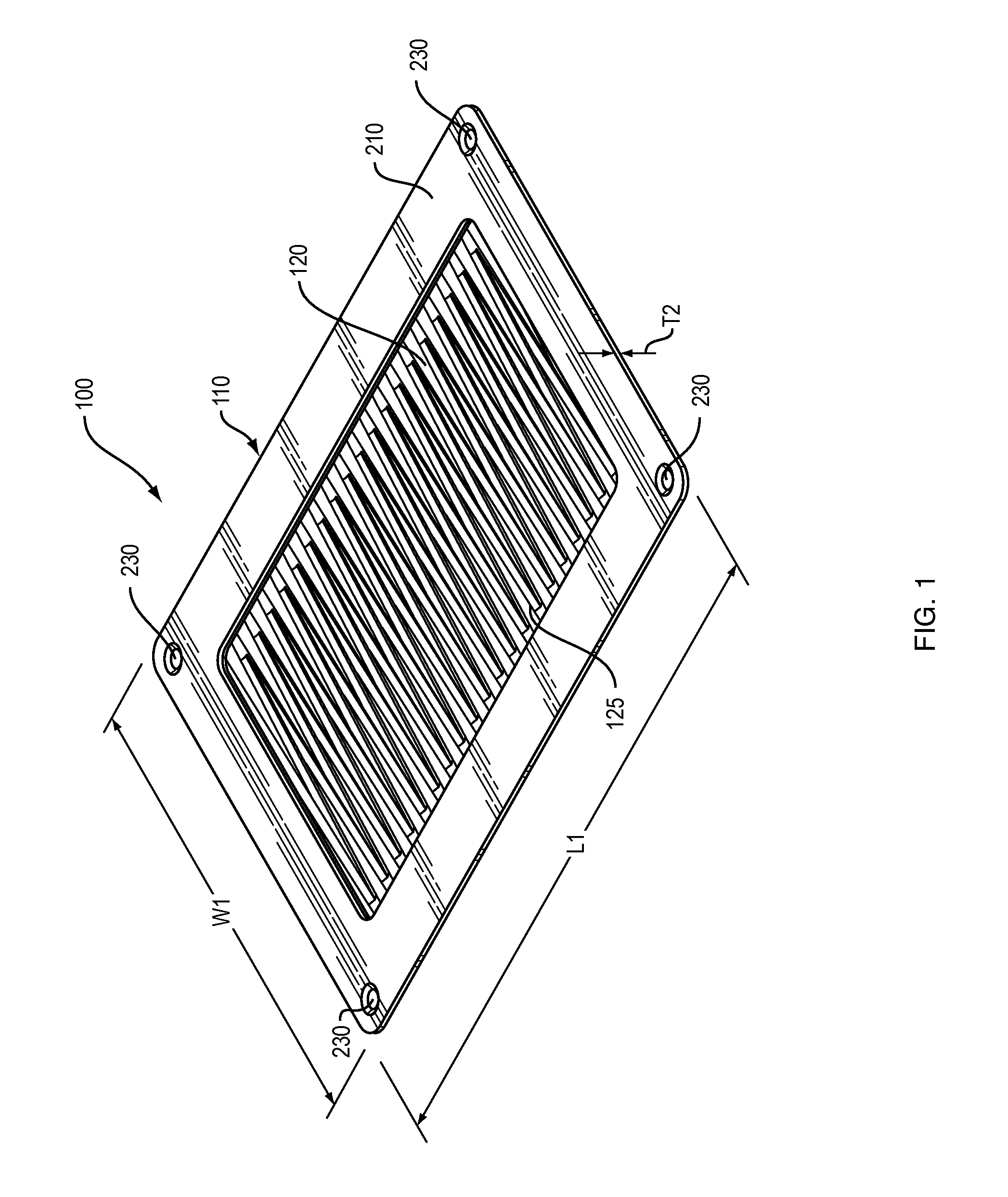
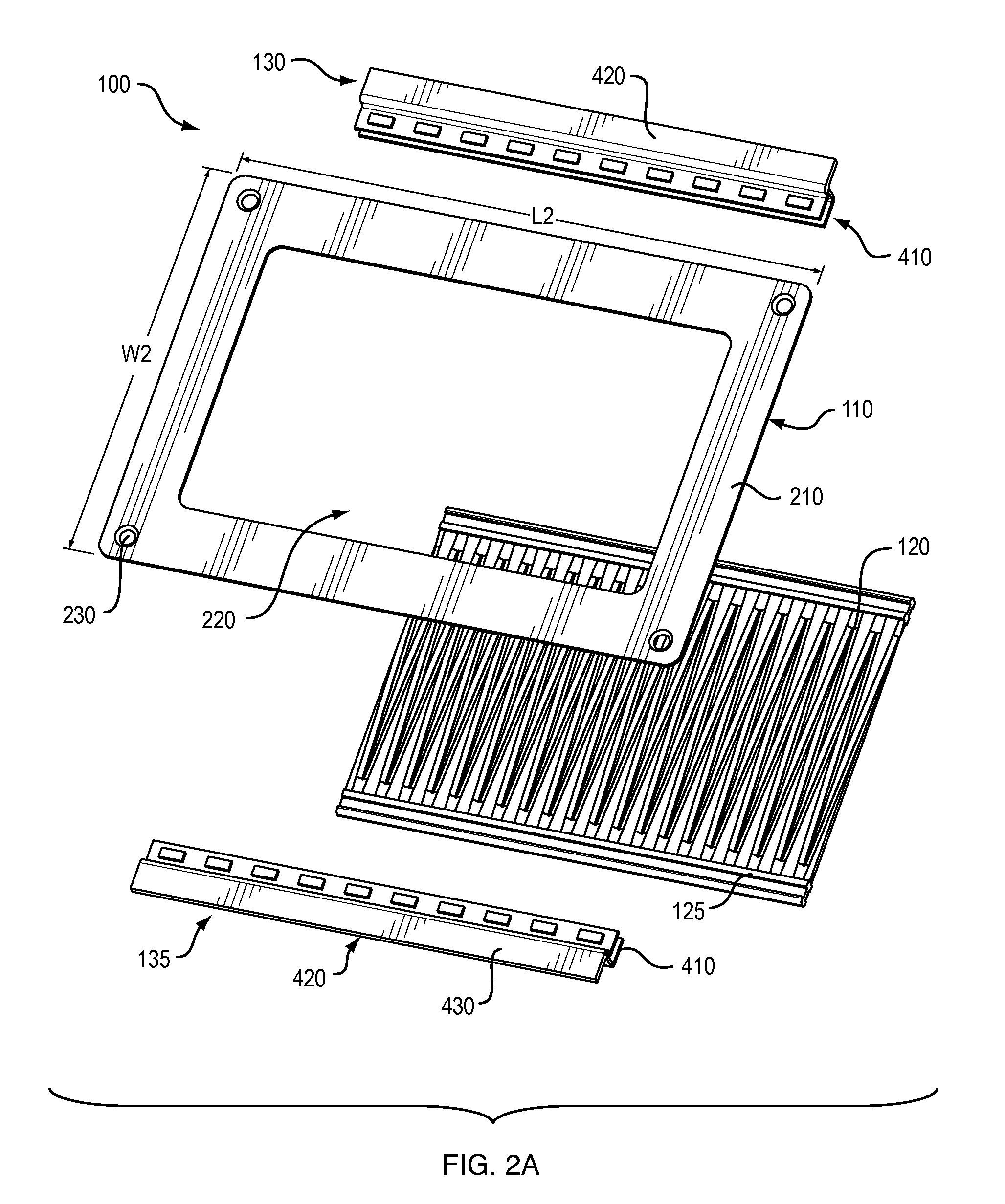
[0049]With reference to FIGS. 1 and 2A, in a preferred embodiment, cable grommet 100 comprises a floor tile mounting flange 110, at least one pair of opposed, overlapping molded finger assemblies 120 and 125, and at least one pair of opposed molded finger mounting flanges 130 and 135.

[0050]In a preferred embodiment, cable grommet 100 is configured to be used with a standard two-foot square raised floor tile, as described in detail below. In this configuration, cable grommet 100 has an approximate length L1 of 10.75 inches (27.3 centimeters) and an approximate width W1 of 8.25 inches (21 centimeters). The thickness or depth of cable grommet 100 is dependent upon the number of pairs of opposed, overlapping molded finger assemblies employed in any specific configuration, as described in detail below. Note that the invention is not limited to any particular type or size of raised floor tile system.

[0051]Floor tile mounting flange 110 defines a generally rectangular perimeter frame 210, ...


PUM


Abstract

Cable grommets for use with raised-floor tiles permit the passage of cables while simultaneously limiting the amount of cool air escaping from under-floor ducts and plenums. The cable grommet includes a floor tile mounting flange, one or more pairs of opposed, overlapping finger assemblies, and one or more pairs of opposed finger mounting flanges for coupling the finger assemblies to the underside of the floor tile mounting flange. The edges of the of the triangularly-shaped fingers are configured to flex around the cables while the interior core section remains generally rigid and parallel to the plane of the floor to restrict the loss of cooling air. Alternatively, the cable grommet includes a floor tile mounting flange and a finger panel defining a sinusoidal cut along its length and a plurality of intersecting short cuts.

Description

CROSS-REFERENCE TO RELATED APPLICATION[0001]This application claims priority to U.S. Provisional Patent Application Ser. No. 61 / 408,794, entitled “Cable Grommet for Use with a Raised Floor,” filed on Nov. 1, 2010. The entire contents of the priority application are expressly incorporated by reference herein.FIELD OF THE INVENTION[0002]The invention relates generally to a cable grommet for use with a raised floor.BACKGROUND OF THE INVENTION[0003]Cooling air is often supplied to data centers and offices via ducts or plenums located under a raised floor. These same under-floor ducts or plenums may also be used for the passage of power and data cables, and openings are often provided in the raised floors to route these cables to the electrical equipment located above the floor. Unfortunately, these openings in the raised floor also allow cooling air to escape, which reduces the overall cooling efficiency of the data center or office. There is a need in the art for devices that can be mo...

Claims


Application Information

Patent Timeline
IPC IPC(8): H02G3/18
CPCH02G3/185
Inventor COTTULI, CARLLINHARES, JR., MANUEL D.
Owner EATON INTELLIGENT POWER LIMITED
Why Eureka
Try Eureka