Exhaust energy recovery system

a technology of exhaust energy recovery and exhaust gas, which is applied in the direction of lighting and heating apparatus, electric generator control, heating types, etc., can solve the problem of substantial amount of energy

Inactive Publication Date: 2012-11-08
E NET
View PDF14 Cites 29 Cited by
  • Summary
  • Abstract
  • Description
  • Claims
  • Application Information

AI Technical Summary

Benefits of technology

[0003]Accordingly, the present invention provides a system that can recover energy from flowing air, such as airflow to and from an HVAC unit that would otherwise be wasted.

Problems solved by technology

The exhaust air from such HVAC units contains a substantial amount of energy that is simply discharged into the surrounding atmosphere and thus wasted.

Method used


Image

  • Exhaust energy recovery system
  • Exhaust energy recovery system
  • Exhaust energy recovery system

Examples


Embodiment Construction

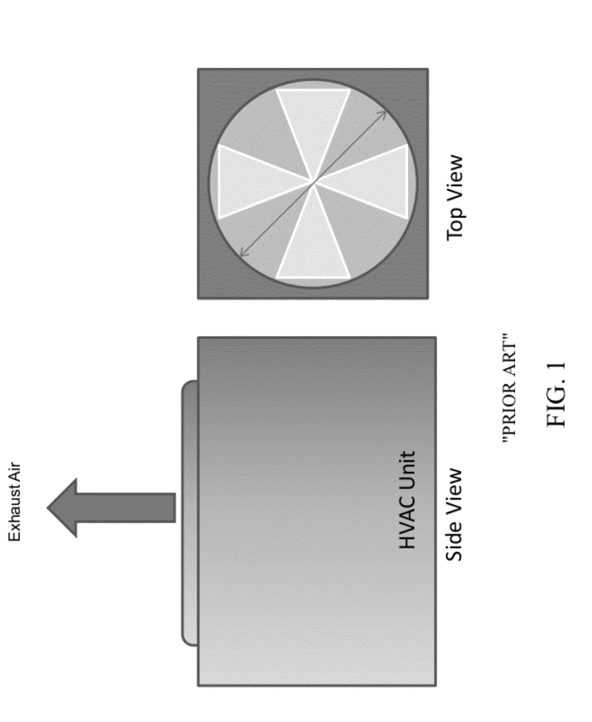
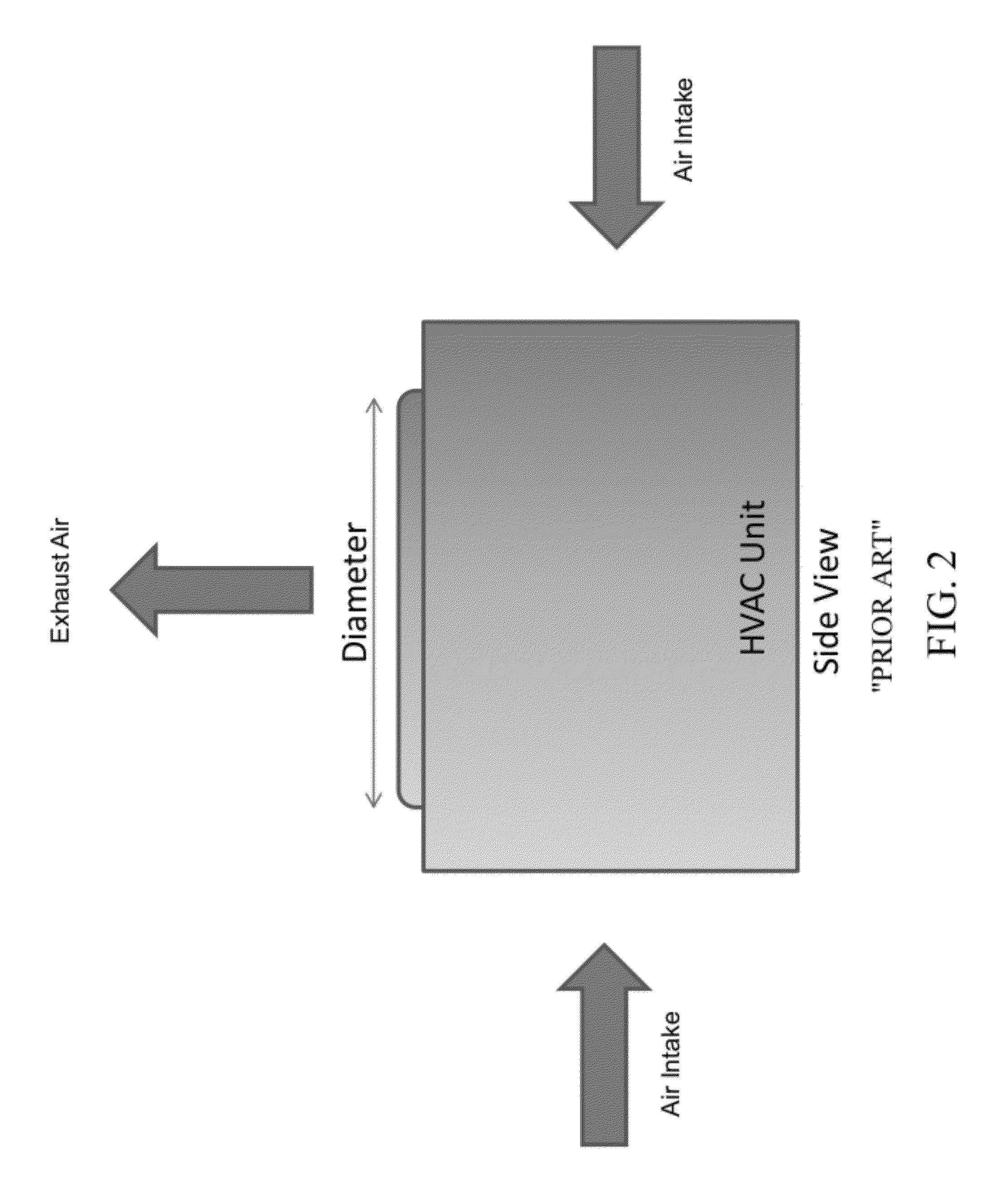
[0037]Referring to FIG. 1, FIG. 1 is a schematic of a conventional HVAC unit, with FIG. 2 showing typical air intake and exhaust directions.

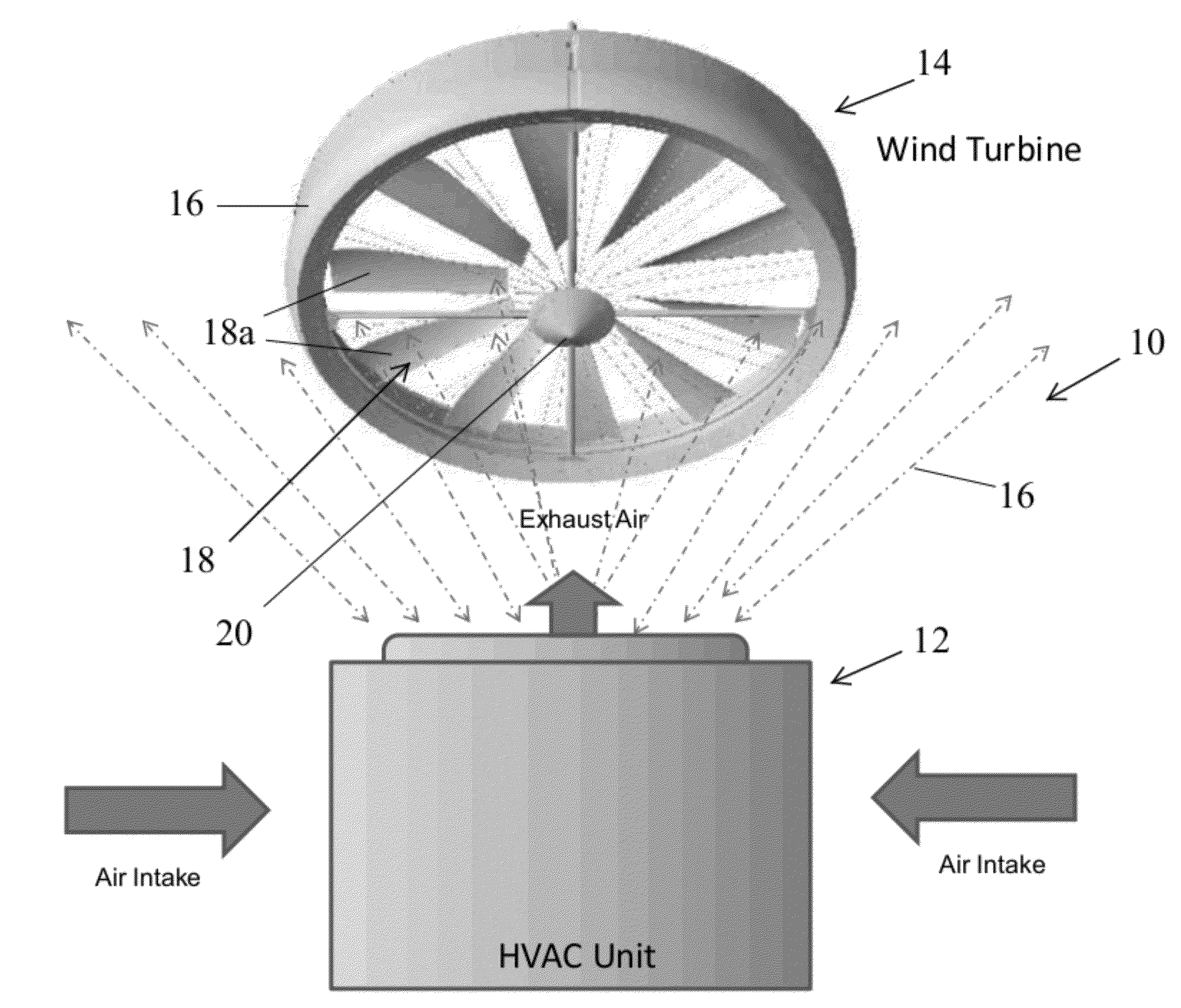
[0038]Referring to FIG. 3, the numeral 10 generally designates an exhaust energy recovery system of the present invention, which incorporates a wind turbine for recovering energy from a ventilation unit, such as a conventional HVAC unit shown in FIGS. 1 and 2. Recovery system 10 includes a ventilation unit 12 and a wind turbine 14, which is positioned to recover at least some of the energy in the exhaust air stream 16 from ventilation unit 12. Although hereinafter the system is described in reference to an HVAC unit, it should be understood that the invention is not so limited and that an HVAC unit is used for illustrative purposes only.

[0039]As generally shown in FIG. 3, wind turbine 14 includes an annular shroud or member 16 and a wind turbine blade assembly 18, which includes a plurality of turbine blades 18a that are mounted for rotation abo...


PUM


Abstract

An energy recovery system includes a fan and a wind turbine adapted to mount adjacent the fan to recover energy from the air flow generated by the fan.

Description

CROSS-REFERENCE TO RELATED APPLICATION[0001]This application claims the benefit of U.S. provisional Pat. applications Ser. No. 61 / 570,458, filed Dec. 14, 2011, and Ser. No. 61 / 479,897, filed Apr. 28, 2011, both entitled EXHAUST ENERGY RECOVERY SYSTEM, which are incorporated by reference herein in their entireties.TECHNICAL FIELD AND BACKGROUND OF THE INVENTION[0002]Typical heating, ventilation, and air conditioning systems (HVAC) employ high power fans that move air at high speed across condenser coils to effect a phase change of refrigerant fluid. The liquefied refrigerant subsequently evaporates once it absorbs heat from a given zone within a facility. The HVAC fans move the heat transfer air at high velocity using electric motors. The exhaust air from such HVAC units contains a substantial amount of energy that is simply discharged into the surrounding atmosphere and thus wasted.SUMMARY OF THE INVENTION[0003]Accordingly, the present invention provides a system that can recover en...

Claims


Application Information

Patent Timeline
Patent Type & Authority Applications(United States)
IPC IPC(8): H02K7/18
CPCF03D9/00Y02E10/72F24F1/50F05B2220/602
Inventor MAHAWILI, IMAD
Owner E NET
Why Eureka
Try Eureka