Workpiece conveyance device

a conveyancing device and workpiece technology, applied in the direction of charging, lighting and heating apparatus, furniture, etc., can solve the problems of reducing the effectiveness of auxiliary stands, high increasing the cost of the entire equipment, so as to achieve safe and easy operation, perform safely and easily, and simple structure

Active Publication Date: 2012-11-15
DAIFUKU CO LTD
View PDF0 Cites 8 Cited by
  • Summary
  • Abstract
  • Description
  • Claims
  • Application Information

AI Technical Summary

Benefits of technology

[0012]According to the configuration of the present invention as set forth in claim 1, a transshipment of the workpiece (the automobile body) between the first and second conveying paths becomes unnecessary by using the first conveying path as a trim line or final line of an automobile assembly line and the second conveying path as a chassis line. Furthermore, the workpiece is conveyed by a long workpiece conveying traveling body formed by the workpiece support carriage and the front and rear two auxiliary carriages adjacent thereto on the first conveying path where the workpiece is fed longitudinally in parallel with a front-rear length direction thereof. Thus, a sufficiently large working floor over an entire periphery of the workpiece can be ensured on the workpiece conveying traveling body, and required works on the first conveying path with respect to the periphery of the workpiece can be performed safely and easily by a worker who gets on the workpiece conveying traveling body. On the second conveying path, only the workpiece support carriage short in front-rear length with the front and rear two auxiliary carriages removed supports and conveys the workpiece while oriented transversely. As a result, it also becomes possible to carry out the work without making the attachment-loaded carriages to be entered under the front and rear of the workpiece get on and off the conveying carriage.
[0013]Furthermore, according to the configuration of the present invention, two places in the front-rear longitudinal direction of the workpiece can be supported from beneath the workpiece individually by the workpiece low-position supporting means provided to the front and rear two auxiliary carriages and the workpiece high-position supporting means provided to the central workpiece support carriage can be folded down under the workpiece, when the workpiece is supported at a low height on the first conveying path. In other words, the workpiece support carriage can be provided with such a workpiece supporting means that can support the workpiece at a high position only when being in the rising posture and can be folded down under the workpiece when not supporting the workpiece and that requires no elevating guide columns. As a result, such elevating guide columns, etc., that constitute a hindrance to works need not be placed at the periphery of the workpiece having been supported at a low position. A variety of works with respect to the periphery of the workpiece having been supported at a low position can be performed safely and easily.
[0014]When the workpiece having been supported at a high position is conveyed perpendicularly and horizontally on the second conveying path, the workpiece low-position supporting means having supported the two places in the front-rear longitudinal direction of the workpiece are removed together with the auxiliary carriages. Thus, the workpiece low-position supporting means do not constitute a hindrance to a variety of works performed by a worker entering under the workpiece as in the case when the workpiece low-position supporting means are placed on the carriage floor surface under both front and rear end portions of the workpiece having been supported at a high position. A variety of works to the lower part of the workpiece having been supported at a high position can also be performed safely and easily.
[0015]It is noted that the workpiece high-position supporting means on the workpiece support carriage may be switched between the folded and rising postures by being driven by juxtaposed actuators. According to the configuration as set forth in claim 2, however, no driving actuators for the workpiece high-position supporting means are required on the workpiece support carriage, and thus, the structure is simple and can be carried out inexpensively. The workpiece high-position supporting means can be configured to have a structure that the workpiece support portions vertically move up and down and to support the workpiece even in the folded posture. In this case, the workpiece support height of the workpiece high-position supporting means in the folded posture is designed to be the lowest height lower than that of the workpiece low-position supporting means of the auxiliary carriages. By properly using the workpiece high-position supporting means of the workpiece support carriage and the workpiece low-position supporting means of the auxiliary carriages, the workpiece can be supported at low positions of at least two, upper and lower levels.
[0016]When the workpiece low-position supporting means on the auxiliary carriages are configured to support the workpiece directly, the workpiece needs to be provided with a supported portion to be supported by the workpiece high-position supporting means and a supported portion to be supported by the workpiece low-position supporting means. According to the configuration as set forth in claim 3, however, the need to provide the workpiece with a supported portion to be supported by the workpiece low-position supporting means is eliminated. As a result, the implementation of the equipment of the present invention is facilitated.
[0017]Further, as described above, the workpiece can be supported at low positions of at least two, upper and lower levels if the workpiece high-position supporting means is configured to be able to support the workpiece even when being in the folded posture. However, even in the structure that the workpiece high-position supporting means cannot support the workpiece when being in the folded posture, the workpiece can be supported at a plurality of heights higher than the workpiece high-position supporting means in the folded posture according to the configuration as set forth in claim 4. Thus, the workpiece support height is changed in accordance with details of works to the periphery of the workpiece, and workability with respect to the periphery of the workpiece can be improved.

Problems solved by technology

However, in the conventional and known variable-length workpiece conveying traveling body as described above, not only does the structure of the workpiece conveying traveling body required in large numbers of the entire equipment become complicated thereby leading to high cost as the entire equipment, but also the size of the auxiliary stands is inevitably restricted since the auxiliary stands are accommodated in a carriage main body or switched into a hanging posture, so that the effectiveness of the auxiliary stands is reduced.
In this respect, cost of the entire equipment also becomes significantly higher.

Method used


Image

  • Workpiece conveyance device
  • Workpiece conveyance device
  • Workpiece conveyance device

Examples


Embodiment Construction

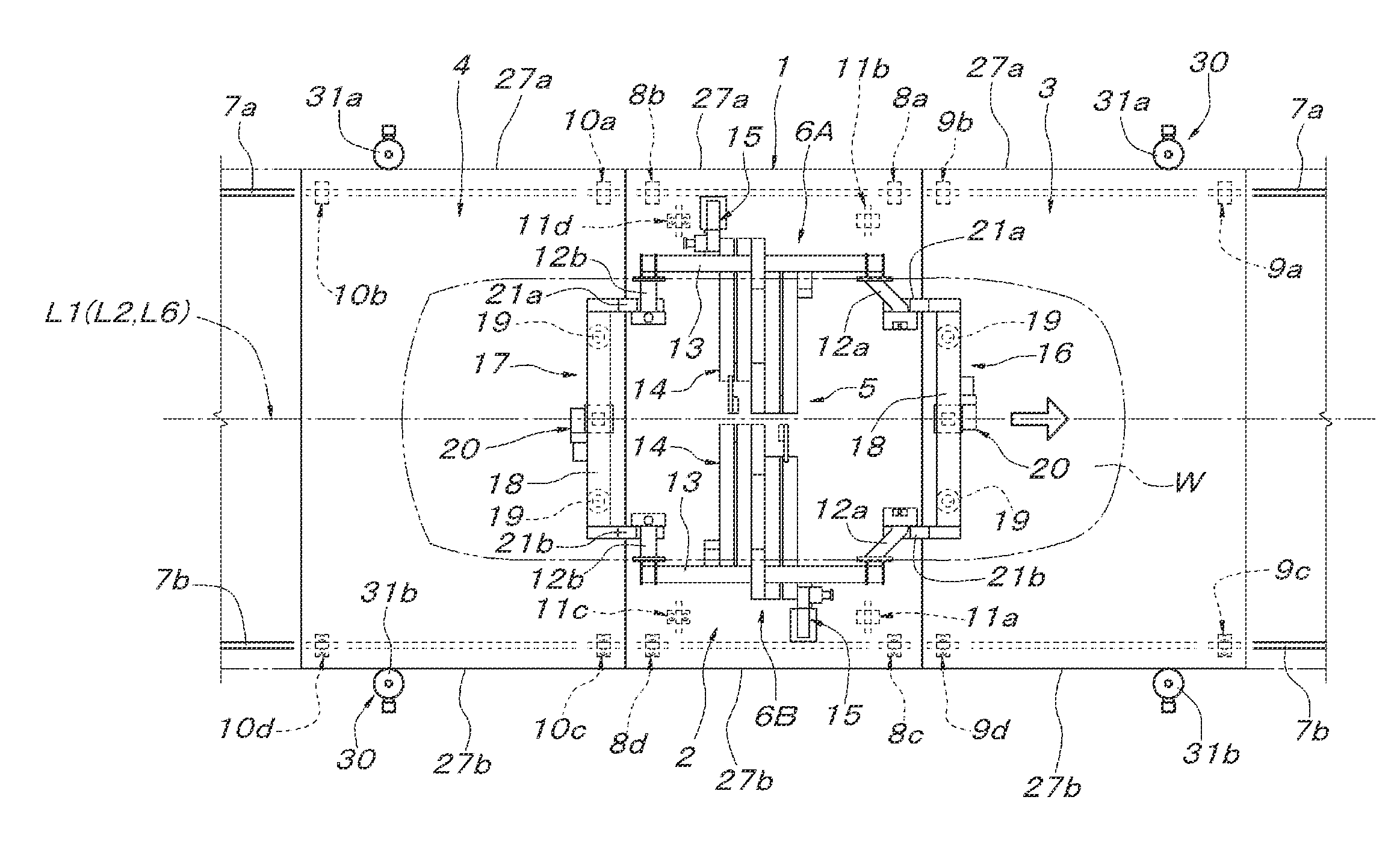
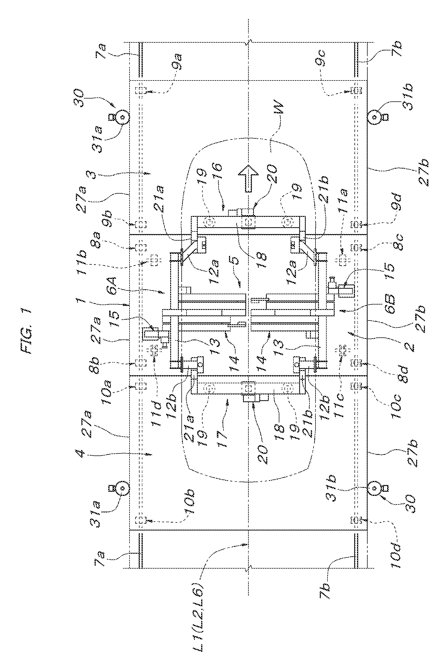
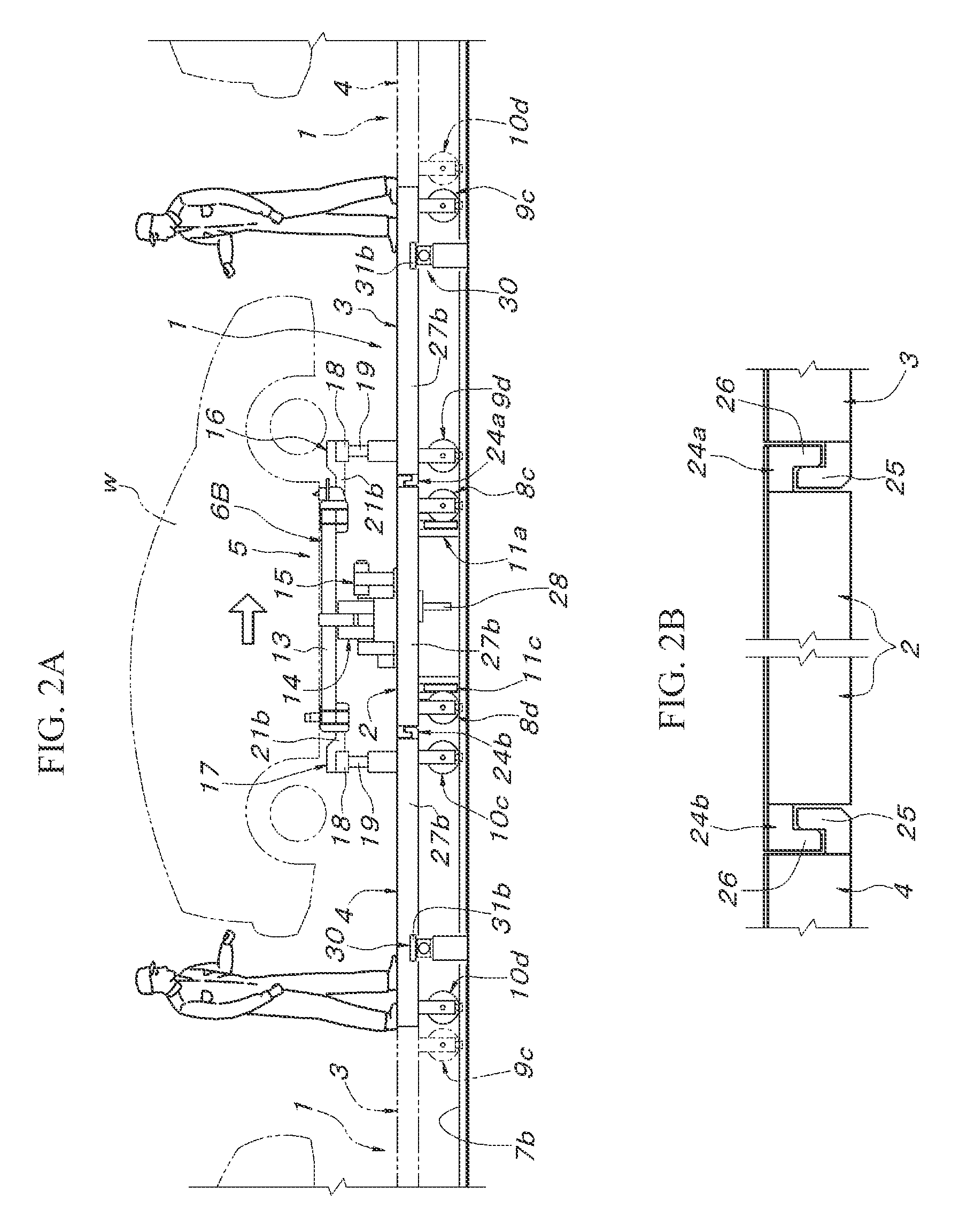
[0040]As shown in FIGS. 1 to 3, a workpiece conveying traveling body 1 in this embodiment is constituted by a central workpiece support carriage 2 and two auxiliary carriages 3 and 4 arranged adjacent to the front and rear in a traveling direction of a first conveying path L1 of the workpiece support carriage 2. The workpiece support carriage 2 has such a horizontally long rectangular shape in plan that a width in a lateral direction is greater than a length in the traveling direction of the first conveying path L1. The workpiece support carriage 2 has an upper surface installed with a workpiece high-position supporting means 5 to support a workpiece (an automobile body) W at a high position. The workpiece high-position supporting means 5 is composed of a pair of left and right elevating support units 6A and 6B respectively supporting both lateral sides of the workpiece W. The workpiece W having been supported by the workpiece high-position supporting means 5 has both front and rear...


PUM


Abstract

Workpiece conveyance device employs a workpiece conveying traveling body composed of a workpiece support carriage supporting a longitudinal central portion of a workpiece and two auxiliary carriages and positioned below both longitudinal end portions of the workpiece. The workpiece support carriage includes a workpiece high-position supporting means switchable between a rising posture of supporting the workpiece at a high position and a folded posture. The two auxiliary carriages nd include workpiece low-position supporting means and to support front and rear two places in the longitudinal direction of the workpiece at a height higher than the workpiece high-position supporting means in the folded posture.

Description

CROSS-REFERENCE TO RELATED APPLICATIONS[0001]The present application is a continuation of pending International patent application PCT / JP2011 / 050875 filed on Jan. 19, 2011 which designates the United States and claims priority from Japanese Patent Application 2010-071858 filed on Mar. 26, 2010, the content of which is incorporated herein by reference.FIELD OF THE INVENTION[0002]The present invention relates to workpiece conveyance device whose workpiece conveying path includes a first conveying path and a second conveying path branched off perpendicularly and horizontally with respect to the first conveying path.BACKGROUND OF THE INVENTION[0003]The above workpiece conveyance device is known in automobile assembly lines, for example. In automobile assembly lines, the first conveying path is used as a trim line or final line where work with respect to a relatively low region of the periphery of an automobile body having been supported on a workpiece conveying traveling body is perform...

Claims


Application Information

Patent Timeline
Patent Type & Authority Applications(United States)
IPC IPC(8): B65G47/22
CPCB62D65/18
Inventor OOE, MASAHIRO
Owner DAIFUKU CO LTD
Why Eureka
Try Eureka