
System for measuring properties of test samples in fluid

a technology of fluid and test sample, applied in the field of photometers, can solve the problems of aging phenomena, inability to monitor the magnitude of the measurement on site, and inability to change the measurement parameters based on aging phenomena

Active Publication Date: 2012-11-15
XYLEM ANALYTICS GERMANY GMBH
View PDF5 Cites 2 Cited by
  • Summary
  • Abstract
  • Description
  • Claims
  • Application Information

AI Technical Summary

Benefits of technology

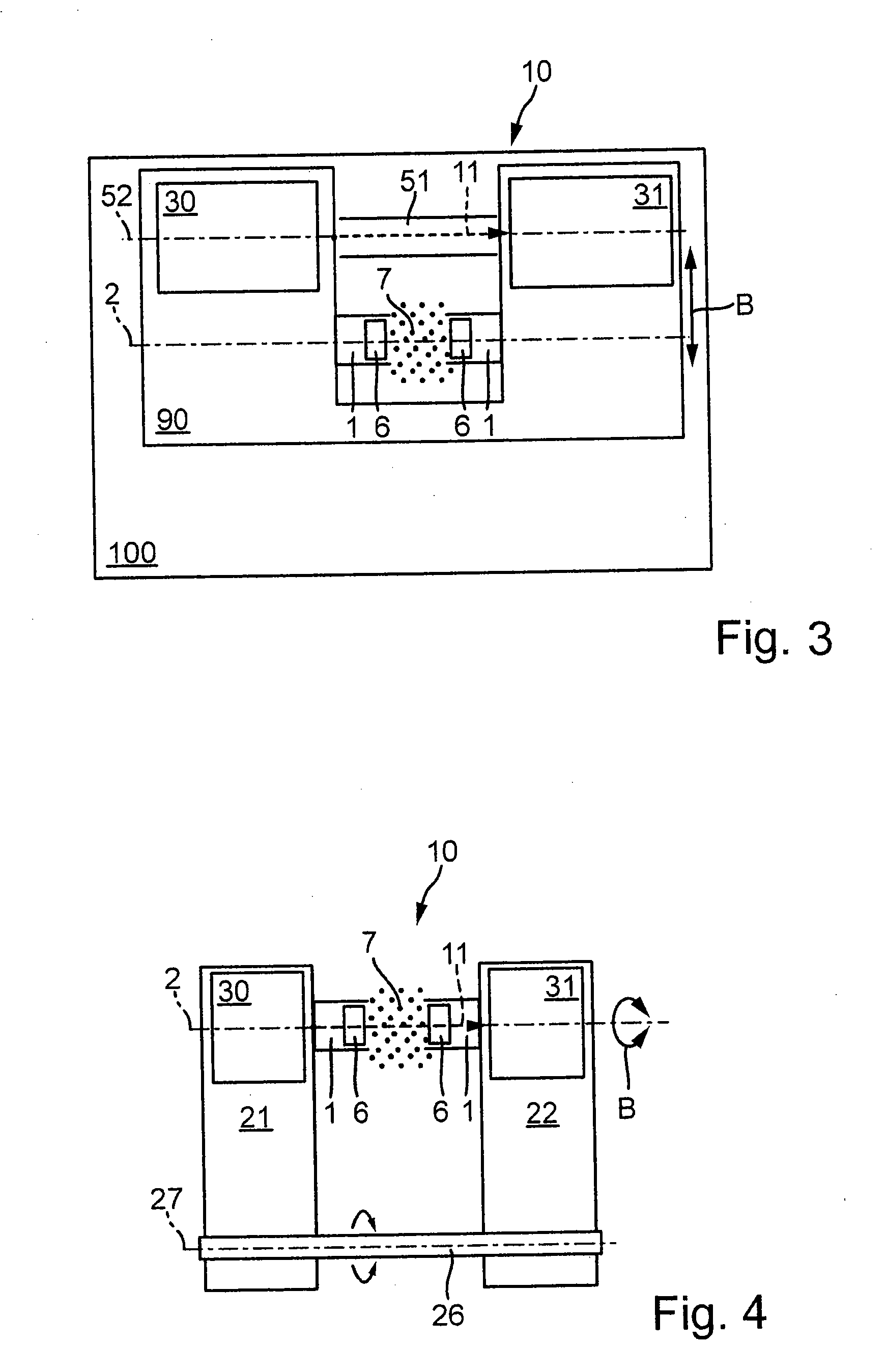
[0010]In this manner a measuring beam can be shifted or moved inside the closed housing of the photometer from, on the one hand, the measuring conduit into, on the other hand, a position in which the measuring beam runs through a reference conduit inside the housing. The deflection of the measuring beam takes place, in accordance with the invention, by a shifting of the carrier part inside the housing of the photometer. The shifting of the carrier part takes place on a previously determined, defined path (B), so that the positional accuracy and zero point tracking of the measuring beam is possible, in spite of using the same transmitter elements and receiver elements. In this manner, the photometer can also be used in any wavelength ranges so that variability in the measuring of different substances, etc. is distinctly increased. On the other hand, no expensive electronic or mechanical division of the measuring beam into a reference component and a measuring component is necessary. The electronic or optical means necessary for this in the prior art can be eliminated. Furthermore, the spatial distance between the measuring conduit and the reference conduit can be selected to be relatively large by a shifting of the position of the measuring beam into, on the one hand, a measuring position (along a measuring conduit) and, on the other hand, the position of a reference conduit. An advantage of this is that the possible disturbances between a reference beam and a measuring beam are reduced. The distance between the measuring conduit and the reference conduit is preferably so great, according to the invention, that suitable optical sealing means, cameras, etc. can be readily housed. In this manner, the photometer, in accordance with the invention, makes possible a relatively high dynamic range and optical cross-talk or disturbance of the measurements is reduced on account of the separated reference conduit. Furthermore, the photometer of the invention has the advantage that the number of necessary components inside the housing is reduced. No different receiving elements or sensors for the reference measurement and the actual measurement in the medium are required. Last, but not least, the photometer in accordance with the invention, ensures a long-term and accurate measurement of photometric magnitudes over a much greater wavelength range than in the prior art. The wavelengths of the measuring beam can be adjusted as desired, in accordance with the absorption strength of the substance to be examined. For example, the photometer, in accordance with the invention, is especially suited for determining substances such as nitrate, nitrite, or other organic compounds in water, or in an aqueous solution.
[0024]According to another advantageous embodiment of the invention, the photometer housing has an oblong tubular shape and is constructed to be completely encapsulated. A complete encapsulation of the housing has the advantage that it is fluid-tight and secure against damage and penetration of elements from the outside. An encapsulated form of the housing is preferably provided with opening means for maintenance and repair of the photometer.

Problems solved by technology

Furthermore, the analysis of liquid media in the laboratory has the disadvantage that a continuous monitoring of measuring magnitudes on site is not possible.
If such photometers are used on site in a liquid for a rather long time period, it can occur that the measuring parameters change based on aging phenomena.

Method used


Image

  • System for measuring properties of test samples in fluid
  • System for measuring properties of test samples in fluid
  • System for measuring properties of test samples in fluid

Examples


Embodiment Construction

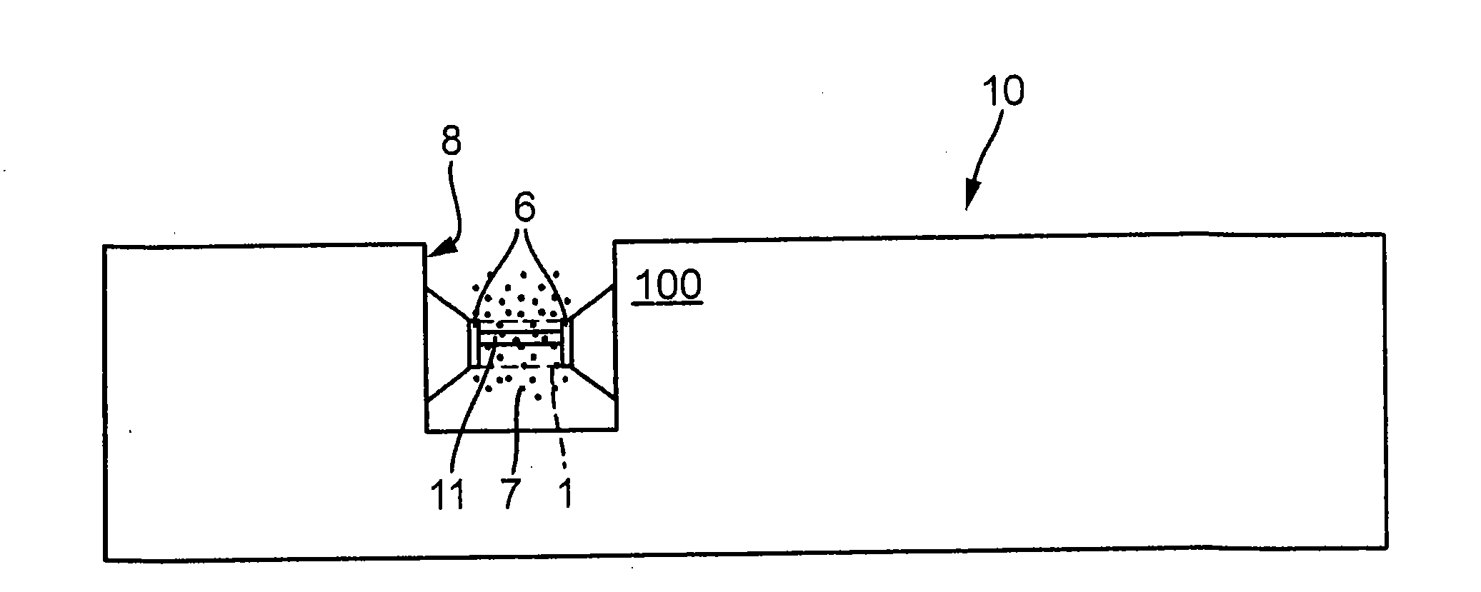
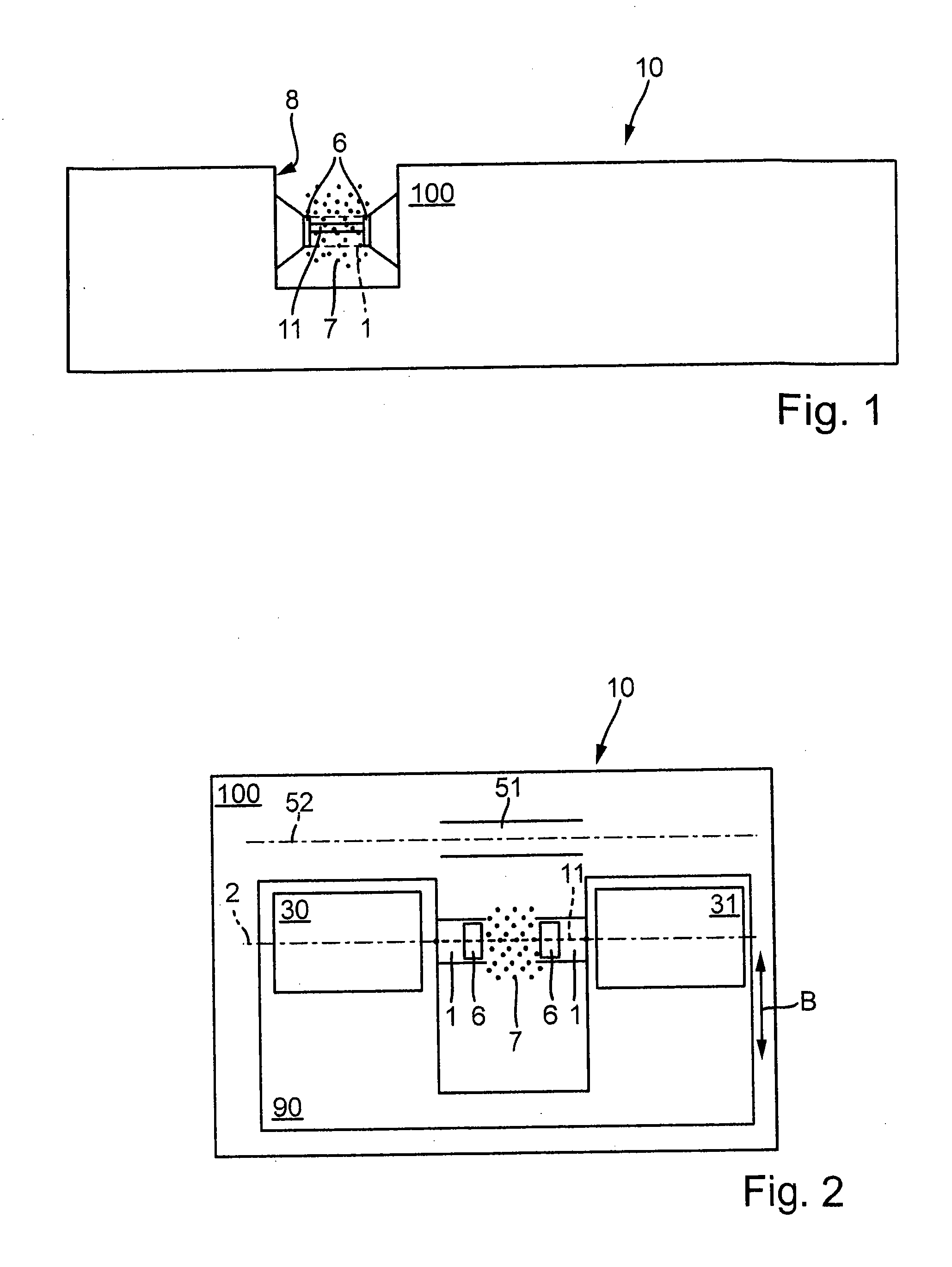
[0034]FIG. 1 shows a schematic top view of a first exemplary embodiment of a photometer, in accordance with the invention, for the on-site measuring of substances in fluids. A tubular, oblong housing 100, that is in this exemplary embodiment approximately one third of the longitudinal extension of the housing 100, is provided with the housing slot 8 that is open to the fluid. The measuring slot 8 is provided here with a depth of approximately one half the diameter of the housing and has two measuring windows 6 on the opposite sides that are transparent for a measuring beam 11 from the interior of the housing 100 of the photometer 10. The housing 100 of the photometer 10 is constructed to be completely encapsulated, i.e., it is fluid-tight and suitable for being completely immersed into a liquid medium. The photometer 10 is provided with connection lines for the supplying of energy and for transmitting measured values to the outside from the liquid medium (not shown in FIG. 1). In th...


PUM


Abstract

A photometer for measuring photometric magnitudes in a liquid medium includes a housing adapted to be introduced into the medium for on-site measurements; and light-emitting measuring beam transmitter and receiver that are arranged behind opposing measuring windows in a measuring slot in the housing, in which the slot is open to the medium. A measuring beam is generated in a measuring conduit in the measuring slot. A reference conduit is included for a reference measurement which is separate from the measuring conduit. At least one carrier part for the measuring beam transmitter and the measuring beam receiver is provided to move on a given path in the housing. The carrier part is constructed to move on the given path from the measuring conduit to the reference conduit and back, for measuring intensity values of the measuring beam in the measuring conduit and in the reference conduit.

Description

CROSS REFERENCE TO RELATED APPLICATIONS[0001]This application claims priority to German Patent Application No. 10 2011 075 530.6, filed May 9, 2011, the contents of such application incorporated by reference herein in its entirety.FIELD OF THE INVENTION[0002]The present invention relates to a photometer for measuring photometric magnitudes in fluids, in particular for the determination of constituents and concentrations of substances in liquid media. The invention relates to such photometers that are adapted for an on-site measuring in liquid media, i.e., with which a measurement can be carried out on site. Such photometers are used, for example, for the determination of constituents in drinking water, sea water, or in wastewater. The sound of the photometer is completely immersed into the water or into the aqueous solution and constituents such as, for example, the nitrate content of the water are measured by optical or electrochemical apparatuses.BACKGROUND OF THE INVENTION[0003]D...

Claims


Application Information

Patent Timeline
IPC IPC(8): G01J1/00
CPCG01N2021/154G01N21/8507
Inventor HOLECZEK, MICHAELSEIBT, HEIKERETTIG, ULRICHAGAH, AMIRHOLDERRIED, MARLENEBENZ, THOMAS
Owner XYLEM ANALYTICS GERMANY GMBH
Learn More