Signal receiving apparatus and method of controlling filters in signal receiving apparatus

a signal receiving apparatus and filter technology, applied in the direction of filters, electrical equipment, transmission, etc., can solve the problems of increasing demodulation error and difficult demodulation of accurate data, and achieve the effect of high-quality demodulation regardless of received signal strength

Inactive Publication Date: 2012-11-15
LAPIS SEMICON CO LTD
View PDF0 Cites 2 Cited by
  • Summary
  • Abstract
  • Description
  • Claims
  • Application Information

AI Technical Summary

Benefits of technology

[0008]One purpose of the present invention is to provide a signal receiving apparatus that i

Problems solved by technology

In the filter having the above-described constitution, however, a demodulation error may increase due to a group delay of the filter as shown in FIG. 1 of the accompanying drawings.
When a short-range (or short distance) communication is carried out and the center frequency of a received signal is deviated from a desire

Method used


Image

  • Signal receiving apparatus and method of controlling filters in signal receiving apparatus
  • Signal receiving apparatus and method of controlling filters in signal receiving apparatus
  • Signal receiving apparatus and method of controlling filters in signal receiving apparatus

Examples


Embodiment Construction

[0024]The multi-filter device of the present invention has a plurality of filters. These filters have different frequency characteristics from each other, and are connected in series. When a frequency signal derived from a received signal is subjected to frequency selection processing by the multi-filter device and received signal intensity is greater than prescribed threshold intensity, then the center frequency of at least one of the filters in the multi-filter device is biased.

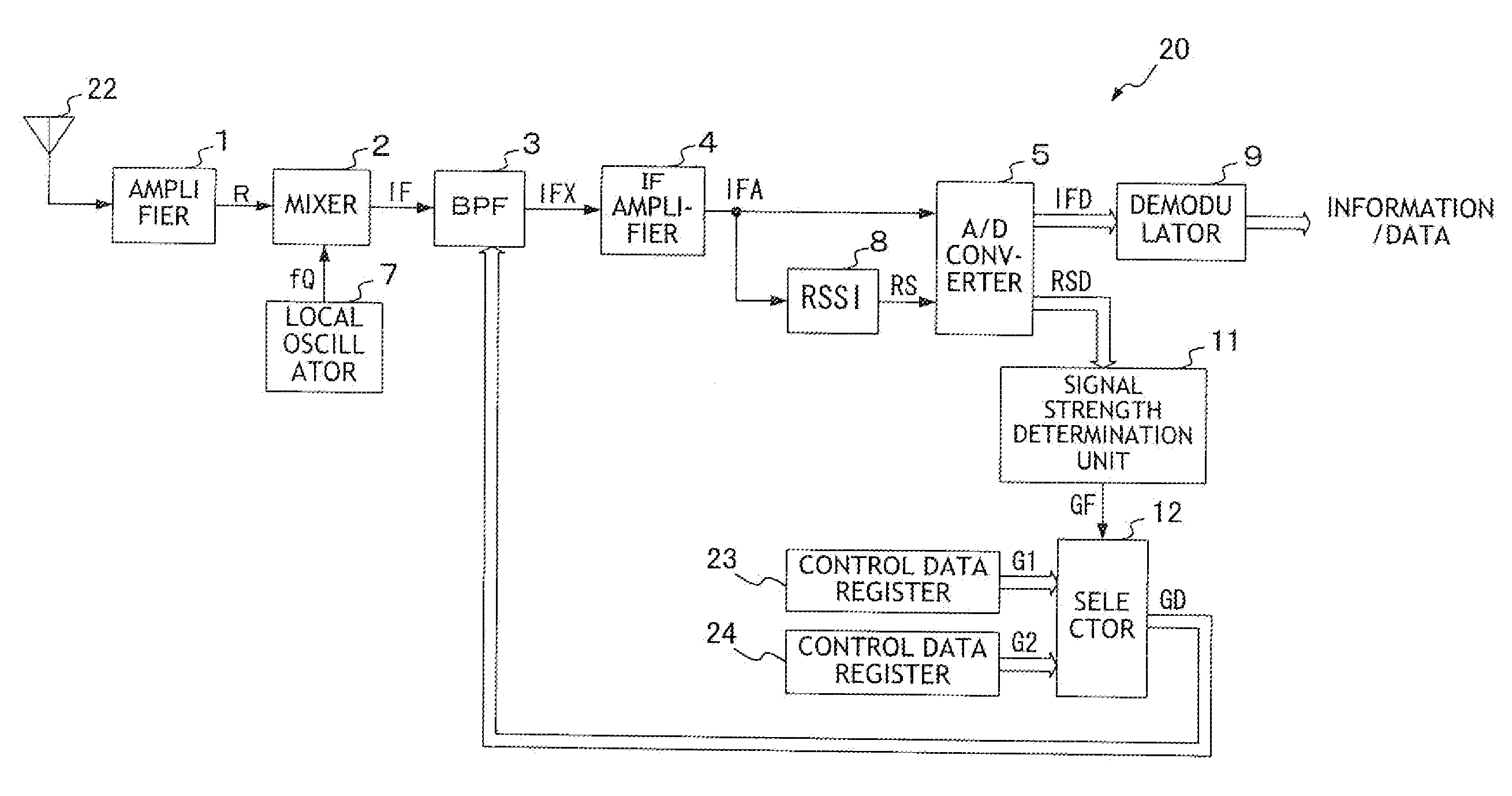
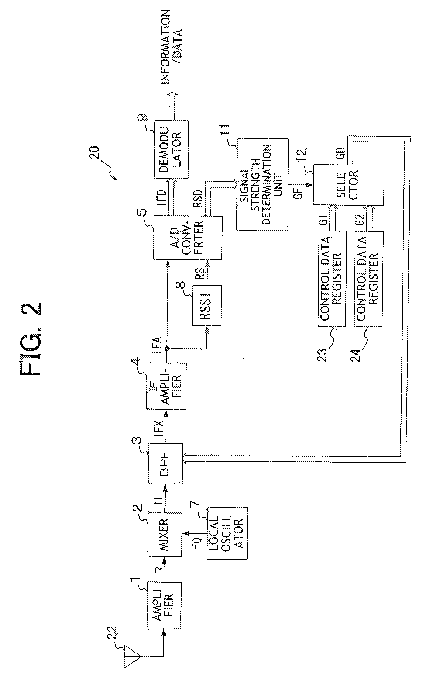
[0025]Referring to FIG. 2, an overall constitution of a signal receiving apparatus 20 according to one embodiment of the present invention will be described.

[0026]In FIG. 2, a transmitted signal wirelessly transmitted from the transmitting apparatus (not illustrated) is received by an antenna 22 of the signal receiving apparatus 20, and an RF signal received by the antenna 22 is supplied to an amplifier 1 as a received signal. The amplifier 1 amplifies the received signal and supplies an amplified signal R ...


PUM


Abstract

A signal receiving device receives an incoming signal to obtain a frequency signal. The signal receiving device has a multi-filter device. The frequency signal is subjected to frequency selection processing by using the multi-filter device. The multi-filter device has a plurality of filters whose frequency characteristics are different from each other. The filters are connected in series. If the received signal intensity is higher than prescribed threshold intensity, the center frequency of at least one of the filters in the multi-filter device is biased.

Description

FIELD OF THE INVENTION[0001]The present invention generally relates to a signal receiving apparatus and in particular it relates to an apparatus that receives and demodulates a signal wirelessly transmitted and also relates to a control method for multiple filters installed in such apparatus.DESCRIPTION OF THE RELATED ART[0002]One of known signal receiving apparatuses operates in the following manner. An IF (intermediate frequency) signal is obtained by converting a received RF (radio frequency) signal into an intermediate frequency band, and this IF signal is subjected to frequency selection processing using an analog band pass filter (hereafter referred to as an analog BPF). Then, the signal after the processing is demodulated so as to restore information and / or data carried on the received RF signal.[0003]The above-mentioned analog BPF is required to have a high Q value in order to increase the interference resistance at the time of signal reception. A filter device for realizing...

Claims


Application Information

Patent Timeline
IPC IPC(8): H04B1/10
CPCH03H11/1291H04B1/1036H03H2011/0494H03H2210/028H03H2210/015H03H2210/025H03H2210/036H03H2210/012
Inventor NAKANISHI, SEIJI
Owner LAPIS SEMICON CO LTD
Why Eureka
Try Eureka