Female terminal for connector

a female terminal and connector technology, applied in the field of female terminals, can solve the problems of complex structure, increased cost, and hardly ensure the contact stability of the female terminal with the male terminal, and achieve the effects of improving the contact stability of the male terminal, high possibility, and easy insertion

Inactive Publication Date: 2012-11-15
YAZAKI CORP
View PDF4 Cites 12 Cited by
  • Summary
  • Abstract
  • Description
  • Claims
  • Application Information

AI Technical Summary

Benefits of technology

[0011]The invention is made in view of the above circumstances, and the purpose of the invention is to provide a female terminal for a connector which allows contact stability with a male terminal to be achieved, has a simple structure, has a box portion readily formed from one sheet of metal plate, and has a good insertion property with respect to a terminal insertion hole of a mat seal.
[0014]In accordance with the first aspect of the invention, since the box portion is formed in a circular cylindrical shape, the female terminal can be readily inserted into the terminal insertion hole without scratching the mat seal.
[0015]In addition, in general, an abutment portion configured by end edges of a metal plate is disposed at an area while avoiding a part having an elastic contact spring or a wall portion for holding a male terminal between the abutment portion and the elastic contact spring. However, in the invention, the abutment portion of the metal plate is disposed on the wall portion for holding the male terminal between the abutment portion and the elastic contact spring, in the peripheral wall of the box portion. Further, the projection portion protruding toward the inside of the box portion is formed on the abutment portion by press deforming the wall portion in a concave shape from the outside of the box portion. Therefore, since the abutment portion tends to open in the press deforming, the contact portion (contact point) as the apex of the projection portion is divided into two points so that the male terminal is clipped and held by the two points together with a contact point at the elastic contact spring side, i.e., total three points. With this, the contact stability with the male terminal can be improved.
[0016]In a case where an abutment portion of a metal plate is not disposed at a wall portion for holding a male terminal between the abutment portion and an elastic contact spring and a projection portion is formed on a position of the wall portion at the inside by forming a concave from the outside as described above, an apex of the projection portion is not divided into two points but is concentrated at one point in a narrow range so that the male terminal is clipped and held by the point together with a contact point at an elastic contact spring side, i.e., total two points. Therefore, the male terminal is possibly rotated because of an instable holding posture. Consequently, the contact stability may be degraded with a high possibility. In this point, in accordance with the first aspect of the invention, it is possible to eliminate such instable holding and to improve the contact conductivity.
[0017]In addition, since the circular cylindrical box portion and the elastic contact spring can be made from an identical metal plate by press processing, it is possible to reduce the cost by simplifying the structure without using two components as in the related example shown in FIG. 6.
[0018]In accordance with the second aspect of the invention, the female terminal can be inserted into the terminal containing chamber of the connector housing through the terminal insertion hole of the mat seal without damaging the mat seal so that the waterproof connector having good quality can be assembled.

Problems solved by technology

However, a problem may arise that the circular female terminal hardly ensures contact stability with a male terminal.
Accordingly, while the contact stability with the male terminal can be improved, problems may arise that the structure is complicated (composed of two components) and the cost is increased.
Consequently, the contact stability may be degraded with a high possibility.

Method used


Image

  • Female terminal for connector
  • Female terminal for connector
  • Female terminal for connector

Examples


Embodiment Construction

[0025]An embodiment of the invention is described below with reference to accompanying drawings.

[0026]A female terminal according to the embodiment is inserted into a terminal insertion hole having a circular cross section on a mat seal attached to a rear end of a connector housing, and thereby the female terminal is formed to be a connector terminal suitable for being used in a waterproof connector.

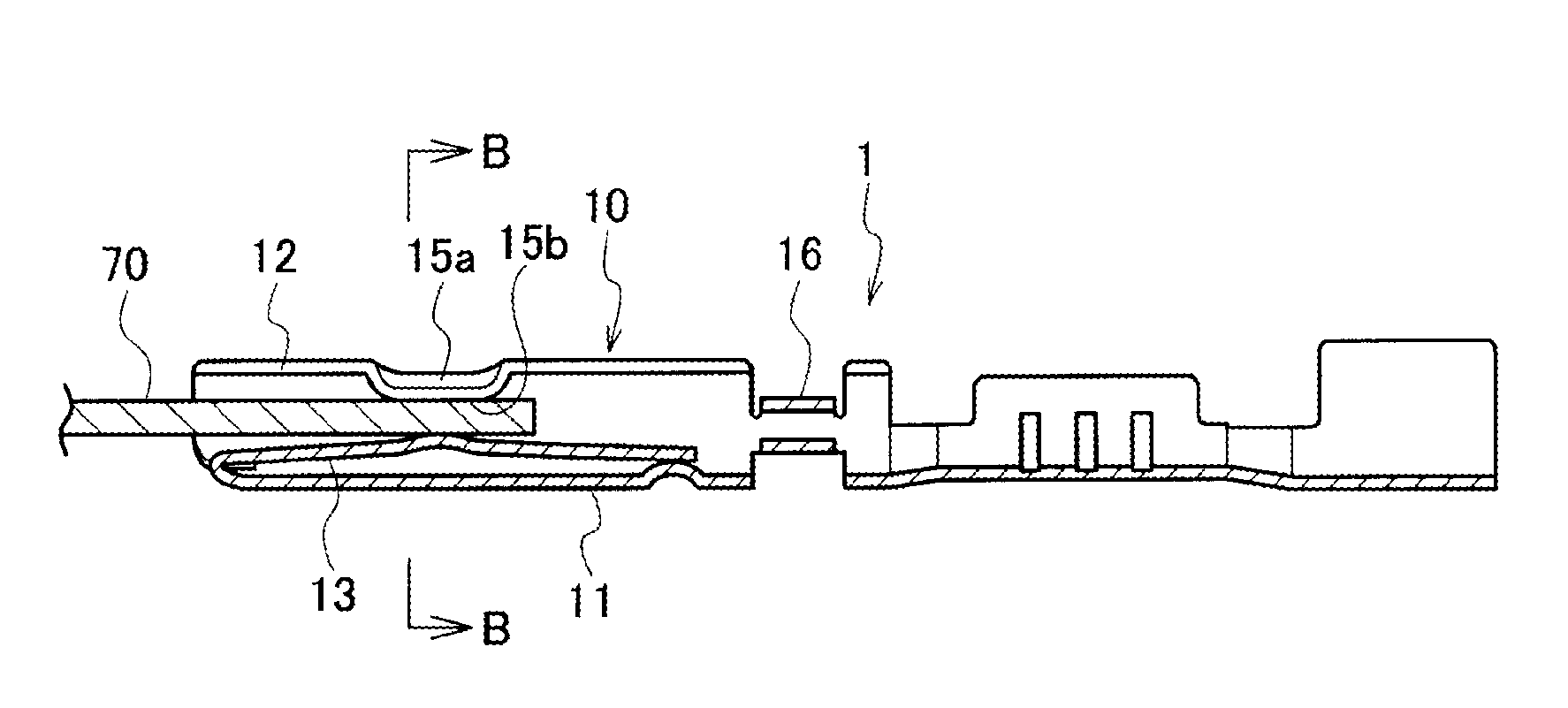
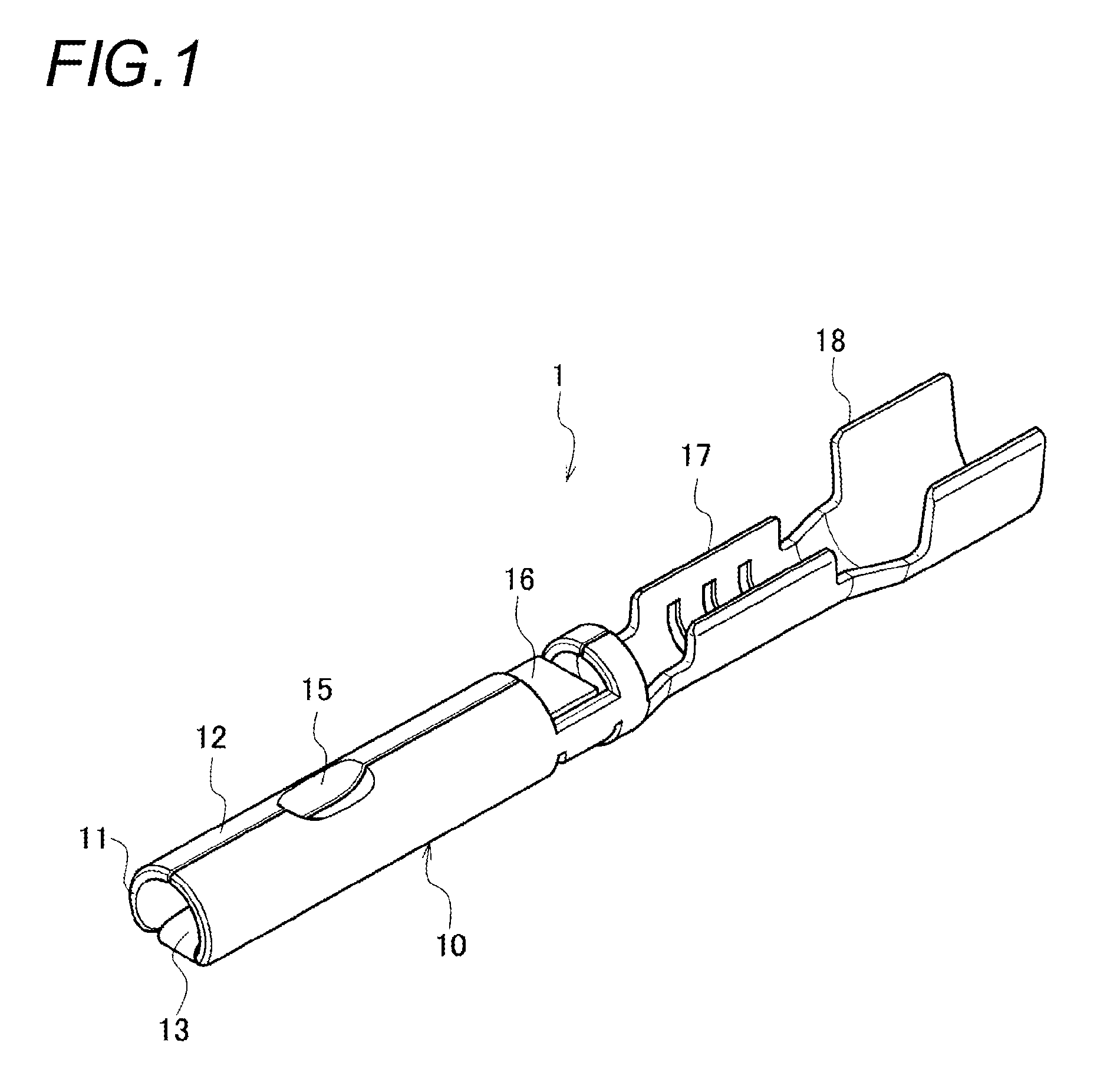
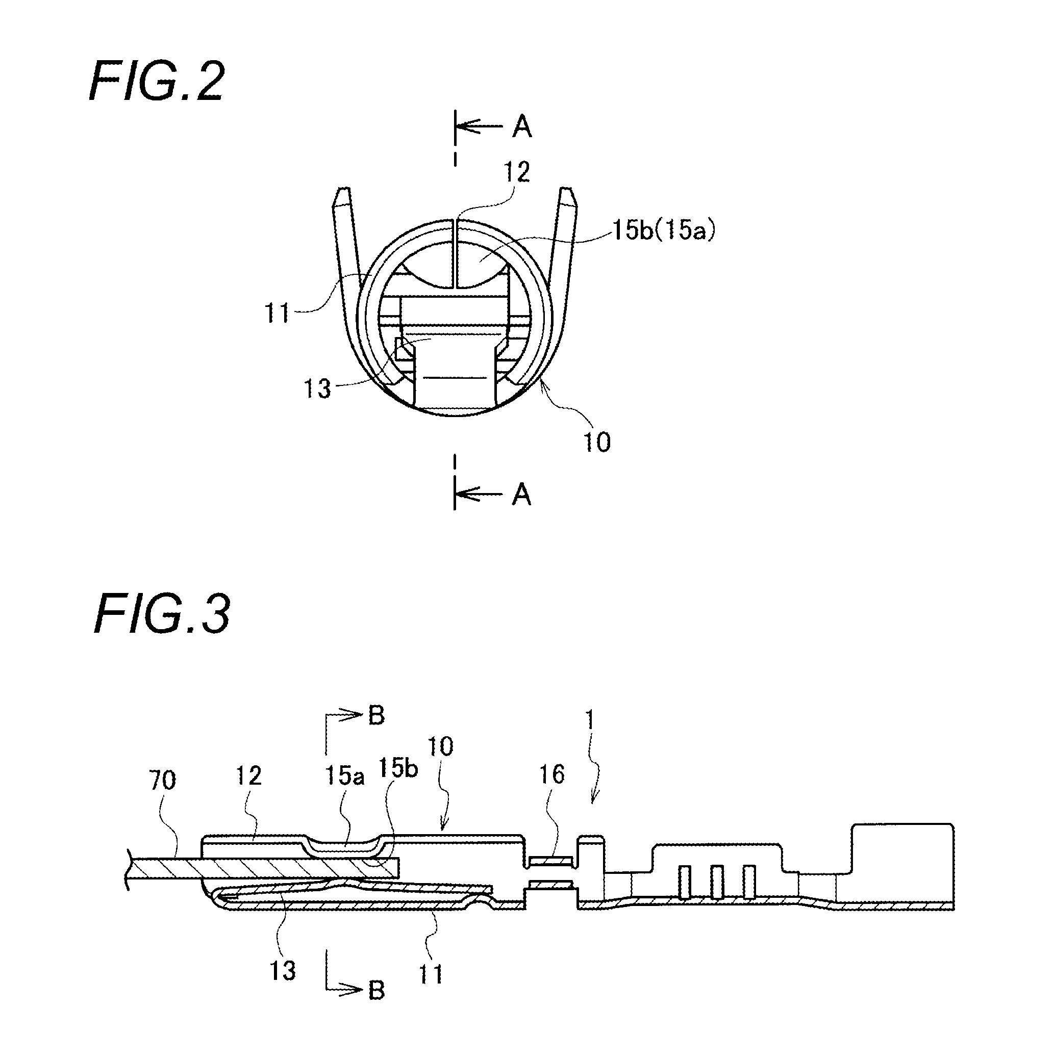
[0027]FIG. 1 is a perspective view showing a structure of the female terminal according to the embodiment. FIG. 2 is an enlarged view showing the female terminal from the anterior side. FIG. 3 is a cross sectional view showing the female terminal taken along a line of arrows A-A in FIG. 2 and showing a state in which a male terminal is inserted into the female terminal. FIG. 4A is a cross sectional view of the female terminal taken along a line of arrows B-B shown in FIG. 3, and FIG. 4B is a cross sectional view showing a state in which a male terminal is inserted into a female terminal ...


PUM


Abstract

A female terminal includes an electric contact portion that has a cylindrical box portion and an elastic contact spring disposed in the inner part of the box portion. An abutment portion of the metal plate is disposed on the upper wall portion of the box portion, and an indent is formed, from the outside of the box portion, at the upper wall portion having the abutment portion disposed thereon. A projection portion is provided at the inside of the box portion, and an apex of the projection portion is made to be a contact portion with respect to the male terminal.

Description

CROSS REFERENCE TO RELATED APPLICATION[0001]This application is a continuation of PCT application No. PCT / JP2011 / 052443, which was filed on Feb. 4, 2011 based on Japanese Patent Application (No. 2010-022858) filed on Feb. 4, 2010, the contents of which are incorporated herein by reference. Also, all the references cited herein are incorporated as a whole.BACKGROUND[0002]1. Technical Field[0003]The present invention relates to a female terminal which is preferable for being used in a waterproof connector with a mat seal (also referred to as a waterproof rubber stopper).[0004]2. Background Art[0005]FIG. 5 is a schematic view showing an example of a waterproof connector with a mat seal described in JP-A-2000-208200.[0006]The waterproof connector is configured such that a mat seal 120 made of a thick plate shaped elastic body (a rubber plate) is attached to a rear end of a connector housing 110, a mat seal cover 130 which is made of a hard resin and is adapted to press the mat seal 120,...

Claims


Application Information

Patent Timeline
Patent Type & Authority Applications(United States)
IPC IPC(8): H01R13/11
CPCH01R13/5208H01R13/113H01R4/185
Inventor ISHIDA, KEIKO
Owner YAZAKI CORP
Why Eureka
Try Eureka