Heat-Resistant Ultrasonic Sensor and Installation Method Thereof

Active Publication Date: 2012-11-22
HITACHI-GE NUCLEAR ENERGY LTD
View PDF6 Cites 21 Cited by
  • Summary
  • Abstract
  • Description
  • Claims
  • Application Information

AI Technical Summary

Benefits of technology

[0030]According to the present invention, defect causing to a structural member of a p

Problems solved by technology

Therefore, the ultrasonic sensor of the single element and

Method used


Image

  • Heat-Resistant Ultrasonic Sensor and Installation Method Thereof
  • Heat-Resistant Ultrasonic Sensor and Installation Method Thereof
  • Heat-Resistant Ultrasonic Sensor and Installation Method Thereof

Examples


embodiment 1

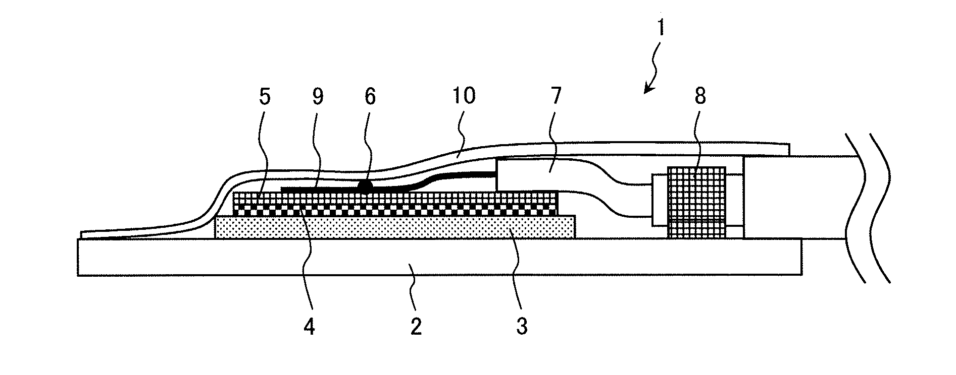
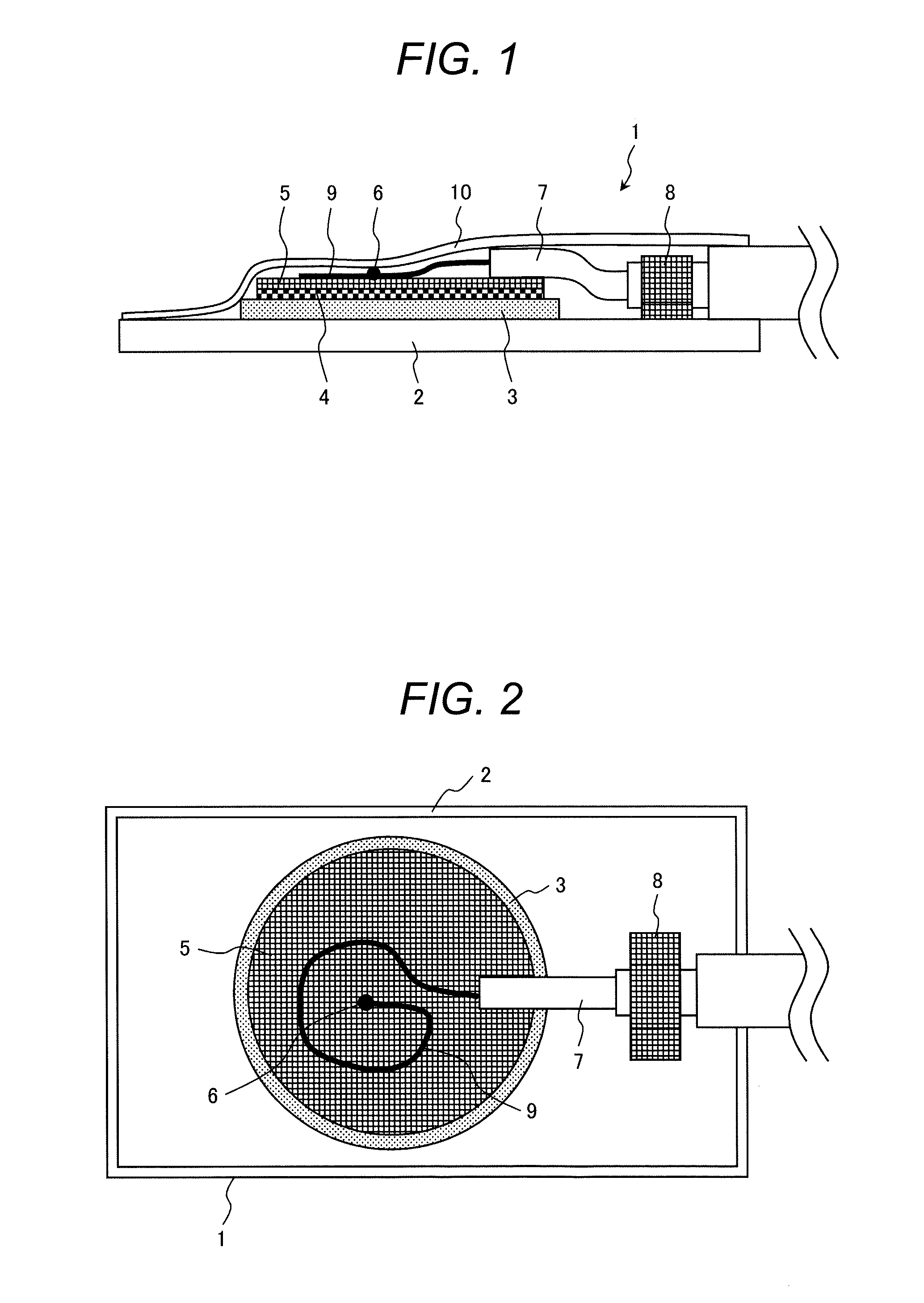
[0041]A heat-resistant ultrasonic sensor according to embodiment 1, which is a preferred embodiment of the present invention, will be explained by referring to FIGS. 1 and 2.

[0042]The heat-resistant ultrasonic sensor 1 of the present embodiment is provided with a thin metal plate (a flexible metal plate) 2, a piezo-electric ceramics film 3, a thin metal film (an electric member) 4, a metal wire mesh 5, and a coaxial cable 7. A shape of the thin metal plate 2 is rectangular and respective shapes of the piezo-electric ceramics film 3, the thin metal film 4, and the metal wire mesh 5 are circular.

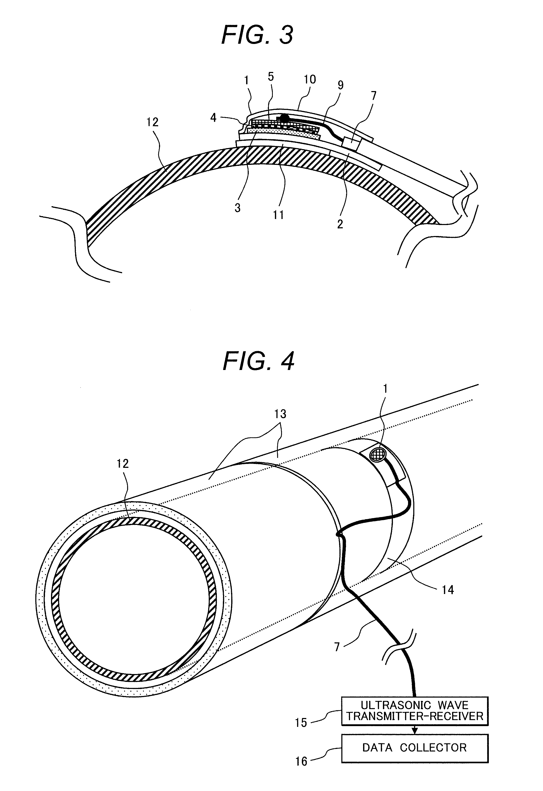
[0043]The thin metal plate 2 is a flexible metal plate and for example, it is made of stainless steel with a thickness of 0.1 mm. The thin metal plate 2 is composed of a metal material having a thermal expansion coefficient of less than ±20% of the thermal expansion coefficient of the metal material composing an inspection object (for example, a pipe 12 shown in FIG. 3) to which the heat-resis...

embodiment 2

[0077]The heat-resistant ultrasonic sensor according to embodiment 2, which is another embodiment of the present invention, will be explained by referring to FIGS. 5 and 6.

[0078]A heat-resistant ultrasonic sensor 1A of the present embodiment has a structure that in the heat-resistant ultrasonic sensor 1 of the embodiment 1, the piezo-electric ceramics film 3 has been replaced with a piezo-electric ceramics assembly 17 including a plurality of crystalline piezo-electric ceramics 17A that are small pieces. The other structure of the heat-resistant ultrasonic sensor 1A is the same as that of the heat-resistant ultrasonic sensor 1.

[0079]A piece of single-crystal piezo-electric ceramics commercially available is cracked into the small pieces of crystalline piezo-electric ceramics 17A for use. Using an inorganic high-temperature adhesive, an undersurface of each small piece of the crystalline piezo-electric ceramics 17A is adhered to the whole top surface of the thin metal plate 2 and a t...

embodiment 3

[0085]A multi channel heat-resistant ultrasonic sensor according to embodiment 3, which is still another embodiment of the present invention, will be explained by referring to FIGS. 7 and 8.

[0086]The multi channel heat-resistant ultrasonic sensor 1B of the present embodiment practically uses a plurality of heat-resistant ultrasonic sensors 1 of the embodiment 1. In other words, the multi channel heat-resistant ultrasonic sensor 1B has a structure that in the plurality of heat-resistant ultrasonic sensors 1, for example, three heat-resistant ultrasonic sensors 1, the thin metal plate 2 and the electric insulating cover 10 are shared. Concretely, in the multi channel heat-resistant ultrasonic sensor 1B, a plurality of (three for example) heat-resistant piezo-electric element portions 19 are disposed in line on the top surface of the flexible thin metal plate 2 with a thickness of, for example, 0.2 mm and each of the heat-resistant piezo-electric element portions 19 is attached on the ...


PUM

PropertyMeasurementUnit
Temperatureaaaaaaaaaa
Lengthaaaaaaaaaa
Electric propertiesaaaaaaaaaa

Abstract

A heat-resistant ultrasonic sensor forms a piezo-electric ceramics film with a thickness of 0.5 mm or smaller and a Curie point of 200° C. or higher on a flexible metal plate. A thin metal film that is an electrode is attached to a top surface of the piezo-electric ceramics film and a metal wire mesh covers the thin metal film and is attached to a top surface of the thin metal film. A core of a heat-resistant coaxial cable is connected to the metal wire mesh at a connection point. The heat-resistant coaxial cable is fixed to the thin metal plate with a metal fixing member that is a ground portion. An electric insulating cover is attached to the thin metal plate and covers the piezo-electric ceramics film, the thin metal film, the metal wire mesh, the connection point, the fixing member, and the core of the coaxial cable.

Description

CLAIM OF PRIORITY[0001]The present application claims priority from Japanese Patent application serial no. 2011-111967, filed on May 19, 2011, the content of which is hereby incorporated by reference into this application.BACKGROUND OF THE INVENTION[0002]1. Technical Field[0003]The present invention relates to a heat-resistant ultrasonic sensor and an installation method thereof and more particularly to a heat-resistant ultrasonic sensor and an installation method thereof that are suitable to monitor a wall thinning, crack propagation and change in a structural materials aiming at the structural member being high temperature in operation such as a nuclear power generation plant, a thermal power generation plant, and a chemical plant is in operation[0004]2. Background Art[0005]Conventionally, in a plant such as a power generation plant, in the periodic inspection of the plant, lowering an inspection object part of the structural member to an inspectable temperature or predicting a re...

Claims


Application Information

Patent Timeline
IPC IPC(8): G01H11/08H01L41/22
CPCG01N29/228Y10T29/42G01N2291/0289G01N29/245
Inventor BABA, ATSUSHIMUSHA, YOSHINORIKOIKE, MASAHIRO
Owner HITACHI-GE NUCLEAR ENERGY LTD
Why Eureka
Try Eureka