
Systems and methods for creating three-dimensional image media

a technology of three-dimensional images and media, applied in the field of media for three-dimensional image generation systems, can solve the problems of not giving three-dimensional images are limited to viewing angles, and methodologies and systems cannot give the appearance of a three-dimensional object suspended in space, etc., to enhance the full three-dimensional effect and reproduce the media content accurately

Active Publication Date: 2012-11-22
YUKICH BARTHOLOMEW GARIBALDI
View PDF54 Cites 65 Cited by
  • Summary
  • Abstract
  • Description
  • Claims
  • Application Information

AI Technical Summary

Benefits of technology

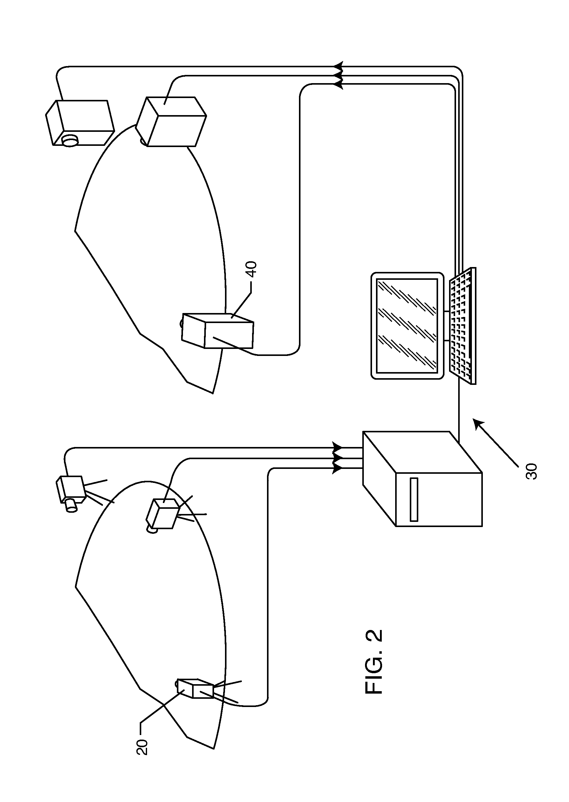
[0020]At least three of the cameras may angularly vary in an x-axis component, a y-axis component, and / or a z-axis component. The cameras in the cylindrical embodiment may vary in the x-axis and y-axis components only, while the cameras in the spherical embodiment may vary in the x-axis, a y-axis, and z-axis components. Preferably, the computer system senses the number of cameras and their relative positioning. In this respect, the computer system may compare the angular positioning of one image captured by one camera at one angle with another image captured by another camera at another angle to determine the relative x-axis, y-axis, and z-axis offset of the cameras relative to one another to calibrate the display device. This media content may be embedded with metadata including, but not limited to, information that includes the x-axis, y-axis, and z-axis offset. The computer system can then accurately reproduce the media content in association with the display device that includes either a projector or an LCD screen.
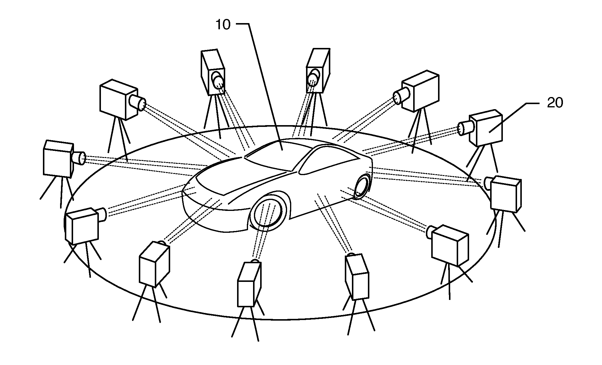
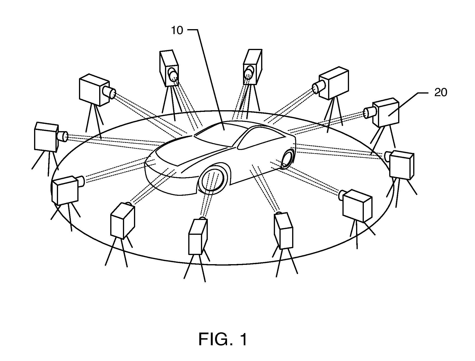
[0021]In an alternative embodiment, the method and process disclosed herein includes a similar method for producing media content that reproduces a three-dimensional object as an image appearing three-dimensionally in association with a display device. This embodiment includes capturing a plurality of images of a three-dimensional object with a plurality of cameras positioned at different angles. The associated computer system creates a recording of the three-dimensional object from these images. Preferably, a plurality of cameras are arranged in and disposed at equidistant intervals around the three-dimensional object to enhance the full three-dimensional effect. Here, at least three cameras may be stacked on one another to provide cylindrical depth to the recording.
[0023]In another aspect of this embodiment, the computer system may sense the number of cameras and their relative positioning by comparing the angular positioning of one image captured by one camera at one angle with another image captured by another camera at another angle. This enables the computer system to determine a relative x-axis, y-axis, and z-axis offset of one camera relative to another camera. This offset allows the computer system to calibrate the display device by aligning the relative x-axis, y-axis, and z-axis offset of the projector or LCD screen used in association with the display device. Such offset information may be embedded into the media content such that the x-axis, y-axis, and z-axis offsets are available during playback.
[0025]Preferably, the computer system is able to sense the number of cameras and their relative positioning. In this respect, the computer system may be able to determine the location of cameras disposed at an intersection point between a line of longitude and at least one of a line of latitude or a Riemannian circle. Having the camera location in hand allows the computer system to further aid in calibrating the display device based on the relative x-axis, y-axis, and z-axis offset of the cameras. In the spherical embodiment, at least three of the cameras should angularly vary in an x-axis component, a y-axis component, and a z-axis component. More specifically, the sensing step includes comparing the angular positioning of one image captured by one camera at one angle with another image captured by another camera at another angle to determine the relative x-axis, y-axis, and z-axis offset of the cameras relative to one another. The computer system may stream the images to the display device in real-time, such as to a projector and or LCD screen.

Problems solved by technology

Thus, while these methods and systems overcome the disadvantage of having a single television screen associated with conventional image displays, these methods and systems do not present a true three-dimensional image in which various angles of the image can be viewed by repositioning the viewing angle of the individual viewing the image.
However, only those immediately in front of the computer monitor or television screen can view the image, and rotation of the image using software is required to view the various angles of the three-dimensional image.
Moreover, such methodologies and systems do not give the appearance of a three-dimensional object being suspended in space and viewable from different views and angles in all directions of a 360° angle by multiple members of an audience simultaneously.
Once again, the viewer must be positioned immediately in front of the screen, and furthermore must wear the specially designed glasses in order to view such images, and the three-dimensional images are limited to the viewing angle in which they are created.
However, this approach has a very limited view angle because the images are inside of the mirror.
However, moving large area LED panels at high frequency creates reliability problems and signal coupling issues.
However, such point scanning methodologies are seriously limited by data rate, resolution, brightness and color.
Although the Tsao, Geng and Mintz et al. processes and systems create a three-dimensional image which appears to be suspended in air and which can be viewed from 360°, the problem with such images is that they are holograms, meaning that they are transparent such that one views the front and back of the image at the same time.

Method used


Image

  • Systems and methods for creating three-dimensional image media
  • Systems and methods for creating three-dimensional image media
  • Systems and methods for creating three-dimensional image media

Examples


Embodiment Construction

[0046]As shown in the accompanying drawings for purposes of illustration, the present invention resides in systems and methods for creating three-dimensional image media for use with a display system that allows a viewer to walk around and see the image in three-dimensions from multiple perspectives, e.g., front, back, left and right sides, or at any one of a number of viewing perspectives 360° around the object, such as from planar, cylindrical or spherical perspectives. The system and method described herein creates the illusion of a three-dimensional image without having to wear special glasses, and is different from a three-dimensional volumetric display, as volumetric images are more like transparent holograms. The system and method uses actual film or digital photography or three-dimensional animation to record or render a plurality of viewable images from a number of different angles or perspectives on a projector or spinning screen. There are different methodologies for prod...


PUM


Abstract

The method for producing media content that reproduces a three-dimensional object as an image appearing three-dimensionally in association with a display device includes capturing a plurality of images of a three-dimensional object with a plurality of cameras positioned at different angles. At least three of the images are synchronized to be reproduced in association with the display device. Then, a computer system assigns at least three synchronized images to the display device viewable from at least three different perspectives to visually replicate the three-dimensional object as captured by at least three cameras at at least three different angles such that the image appears three-dimensional when moving among the at least three perspectives as if moving around the three-dimensional object itself.

Description

BACKGROUND OF THE INVENTION[0001]The present invention generally relates to media for three-dimensional image generation systems. More particularly, the present invention relates to systems and methods for creating three-dimensional image media for use with a display system that reproduces the appearance of a three-dimensional object as if the object is suspended in air and appears solid as the viewer changes viewing perspectives by, for example, walking around the display system.[0002]Creating images which appear to be suspended in the air are well known. For example, U.S. Pat. No. 4,979,026 to Lang et al. discloses a 360° viewing system for presenting an image in space that is rotated extremely rapidly so that an entire audience, regardless of an individual's position about the viewing system, can view the same image substantially simultaneously and continuously. An electronic image rotation system distorts, processes and rotates an image upon a cathode ray tube and a parabolic mi...

Claims


Application Information

Patent Timeline
Patent Type & Authority Applications(United States)
IPC IPC(8): H04N13/02H04N13/393H04N13/363H04N23/90
CPCH04N13/0493H04N13/0242H04N5/247H04N13/0497H04N13/243H04N13/393H04N13/398H04N13/363H04N23/90
Inventor YUKICH, BARTHOLOMEW GARIBALDI
Owner YUKICH BARTHOLOMEW GARIBALDI
Learn More