Image processing device and image processing method

a technology of image processing and image, which is applied in the field of image processing device and image processing method, can solve the problems of difficult to see the corresponding image, uneven brightness of synthetic images, etc., and achieve the effects of less luminance unevenness, improved user visibility, and preventing user discomfor

Inactive Publication Date: 2012-11-22
DENSO CORP
View PDF19 Cites 26 Cited by
  • Summary
  • Abstract
  • Description
  • Claims
  • Application Information

AI Technical Summary

Benefits of technology

[0027]According to the configuration described in (1) to (6), the generated synthetic image has less luminance unevenness, and thus it is possible to prevent the user from having discomfort.
[0028]According to the configuration described in (2), since other camera images are adjusted based on the ideal camera image having the highest average luminance, the visibility for the user can be improved.
[0029]According to the configuration described in (3), since the highest average luminance is prevented from being extremely heightened, the visibility for the user can be improved.
[0030]According to the configuration described in (4), in the case where the bright image and the dark image coexist, the adjustment is made based on the bright image, and thus the dark image can be brightened.
[0031]According to the configuration described in (5), in the case where the bright image and the dark image coexist, the luminance can be adjusted based on the average luminance for each camera image, and thus image degradation can be prevented.
[0032]According to the configuration described in (7) to (11), an image with various luminance distribution variations, which is captured by a camera mounted on a vehicle that is put into various situations, can be optically adjusted.

Problems solved by technology

However, in the vehicle surrounding image display system, if one sheet of synthetic image is generated after AGC is performed with respect to every one of the plurality of camera images, brightness unevenness may occur in the synthetic image.
Further, if the AGC is performed after the plurality of camera images are synthesized into one sheet of vehicle surrounding image, the image having the highest luminance becomes further brighter due to the influence of the darkest image, and thus it may become difficult to see the corresponding image.

Method used


Image

  • Image processing device and image processing method
  • Image processing device and image processing method
  • Image processing device and image processing method

Examples


first embodiment

Vehicle

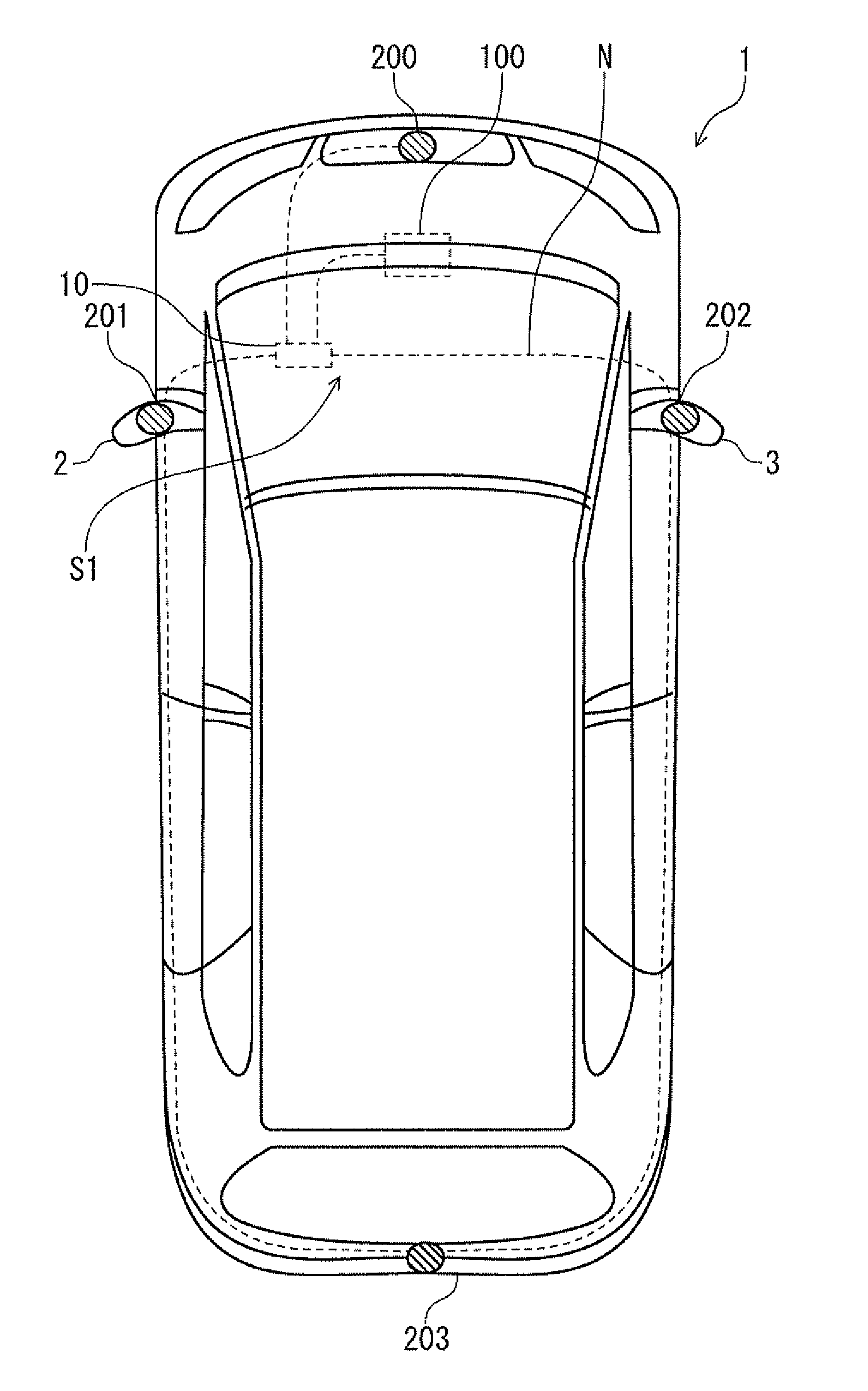
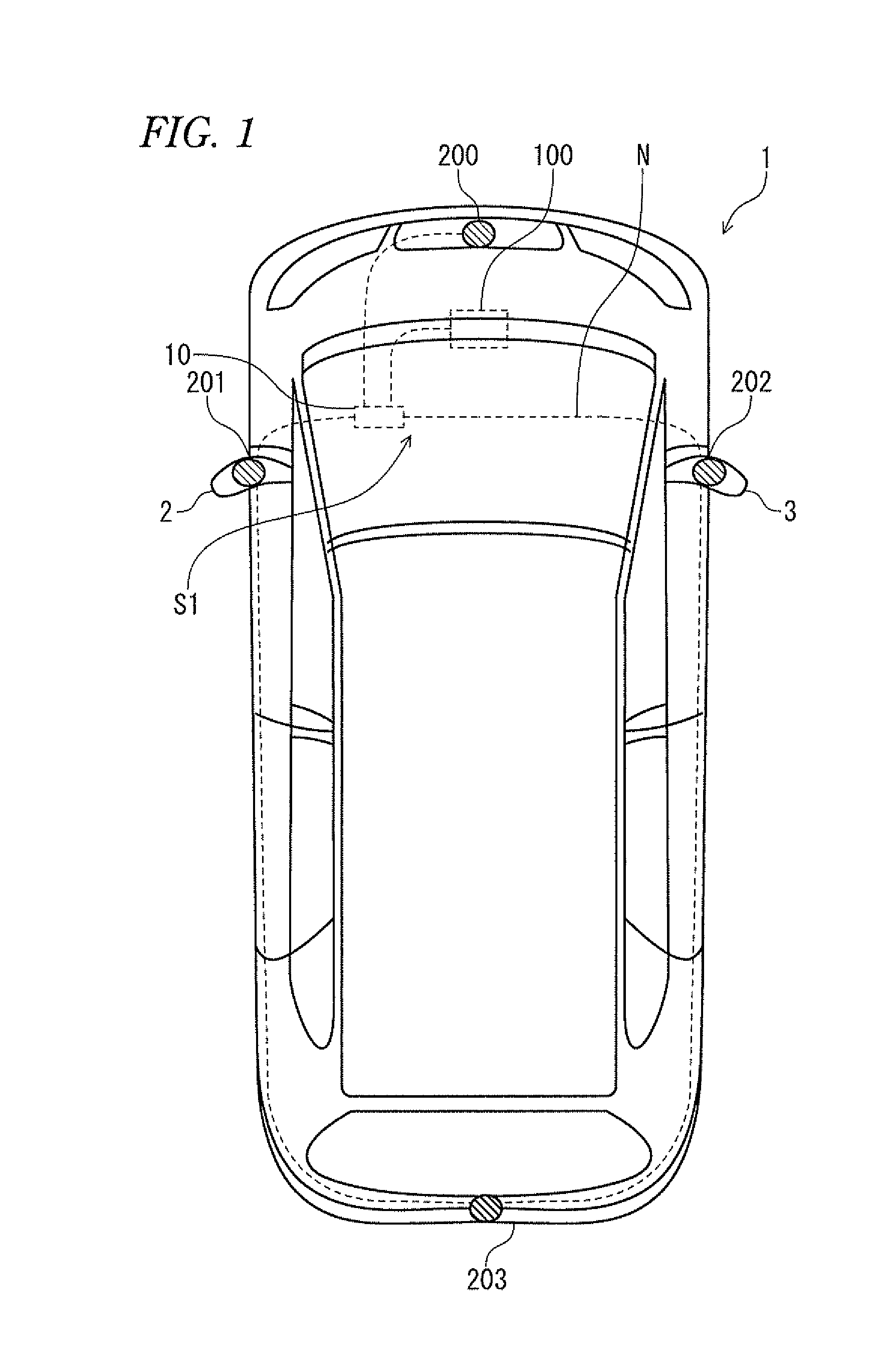
[0061]First, a vehicle surrounding image display system mounted on a vehicle in which an engine or a traveling electric motor, which is a driving source, is installed will be described on the basis of FIG. 1.

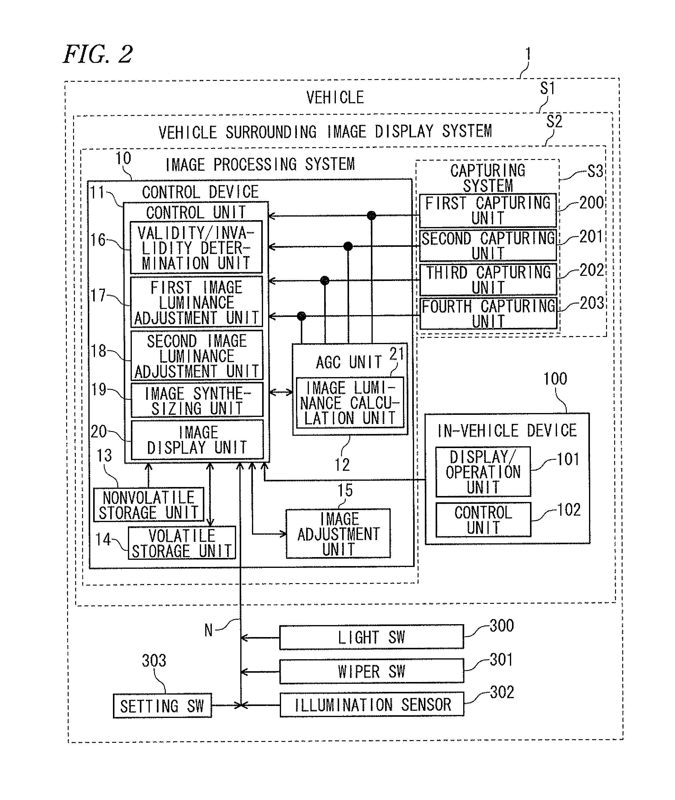
[0062]A vehicle surrounding image display system S1 includes an image processing system S2, an in-vehicle device 100, various kinds of switches and sensors, which are electrically connected to an in-vehicle network N.

[0063]The image processing system S2 includes a control device 10, a first capturing unit 200, a second capturing unit 201, a third capturing unit 202, and a fourth capturing unit 203, which constitute a capturing system S3.

[0064]The control device 10 is installed below a passenger seat of a vehicle 1. The in-vehicle device 100 is installed between a driver seat and the passenger seat in a dashboard of the vehicle 1. The first capturing unit 200 is installed in a front portion of the vehicle 1, the second capturing unit 201 is installed in a left side mirror ...

modified example 1

[0158]In the first embodiment, in step S1002 of FIG. 4, the AGC unit 12 determines whether or not the luminance devoted to the pixels exceeds the constant threshold value when calculating the average luminance of the images Z1 to Z4 received from the first to fourth capturing units 200 to 203. As described above, if the luminance exceeds the threshold value, the AGC unit 12 does not make the luminance included in the sum of the luminance in calculating the average luminance, and further, does not make the luminance included in the total number of pixels. However, the control unit 11 of the control device 10 may determine the brightness of the outside of the vehicle and calculate the average luminance based on the threshold value that corresponds to the brightness of the outside of the vehicle.

[0159]For example, in the case of determining that the outside of the vehicle is dark, the control unit 11 sets the threshold value to a threshold value that is higher than the above-described ...

modified example 2

[0163]In the first embodiment as described above, in step S2001 of FIG. 7, the control unit 11 receives the signal from the setting switch 303 through the in-vehicle network N, and determines whether the received signal indicates setting 1 or setting 2. If it is determined that the received signal indicates setting 1, the control unit 11 performs the first image luminance adjustment process as shown in FIG. 10, and if it is determined that the received signal indicates setting 2, the control unit 11 performs the second image luminance adjustment process as shown in FIG. 12. However, the control unit 11 determines whether or not the difference between the highest average luminance and the lowest average luminance among the average luminances of the images Z1 to Z4 received from the AGC unit 12 is larger than the prescribed value, and if it is determined that the difference is larger than the prescribed value, the control unit 11 turns on the first flag to perform the first image lumi...


PUM


Abstract

An image processing device configured to be installed in a vehicle includes an image acquirer, an image selector, a first luminance adjuster, a synthetic image generator, and an image provider. The image acquirer acquires camera images captured by cameras provided on the vehicle. The image selector selects one of the camera images as a representative image based on luminances of the camera images. The first luminance adjuster adjusts a luminance of at least one of the other camera images based on a luminance of the representative image. The synthetic image generator generates a synthetic image showing a periphery of the vehicle, based on the representative image and the other camera images the luminance of at least one of which has been adjusted by the first adjuster. The image provider outputs, to a display device installed in the vehicle, information corresponding to the synthetic image.

Description

TECHNICAL FIELD[0001]The present invention relates to a technology to adjust the luminance of a plurality of camera images that are synthesized.BACKGROUND ART[0002]A technology to process an image input from a camera and display the processed image on a display screen is known. For example, there is a camera image processing called AGC (Automatic Gain Control).[0003]In general, AGC refers to the control that makes an image displayed on a display screen not too dark and not too bright, through an electrical circuit or the like, by performing a process of increasing the entire brightness if an average brightness of an image signal input from a camera is weak, while performing a process of decreasing the entire brightness if the average brightness of the image signal is strong. Such a camera image processing technology is disclosed, for example, in Japanese Unexamined Patent Application Publication No. 11-136571 (Patent Document 1).[0004]Specifically, with respect to luminance devoted ...

Claims


Application Information

Patent Timeline
Patent Type & Authority Applications(United States)
IPC IPC(8): H04N7/18
CPCB60R1/00B60R2300/30G06K9/00812G06V20/586
Inventor MURAKAMI, MASAHIKOASAYAMA, NOBUNORI
Owner DENSO CORP
Why Eureka
Try Eureka