Lens shifting device and projection display device including the same

a technology of projection display and lens shifting, which is applied in the direction of printers, instruments, cameras focusing arrangements, etc., can solve the problems of increased cost, increased size and weight of lens shifting devices, and deterioration of position accuracy between the center axis of the projection lens and the video optical axis or slider sliding, etc., to achieve simple structure and high positional accuracy and sliding. slidability

Active Publication Date: 2012-11-22
SHARP NEC DISPLAY SOLUTIONS LTD
View PDF6 Cites 8 Cited by
  • Summary
  • Abstract
  • Description
  • Claims
  • Application Information

AI Technical Summary

Benefits of technology

[0020]According to the present invention, the lens shifting device has a simple structure and a small number of components, is compact and lightweight, and has high positional accuracy and slidability.

Problems solved by technology

As a result, the positional accuracy between the center axis of the projection lens and the video optical axis or the slidability of the sliders may deteriorate.
This creates a problem in which the size and weight of the lens shifting device increase.
Processing accuracy is required for the guide shaft or the roller support mechanism, which increases costs.
Further, when a metal is used for the guide shaft in view of slidability and processing accuracy, due to heat generated by the use of the projection display device, thermal expansion or thermal contraction easily occurs in the guide shaft or the roller support mechanism.
As a result, the gap between the guide shaft or the roller support mechanism and the slider changes, creating a problem in which there would be a reduction in positional accuracy or slidability.
Thus, no improvement in accuracy is required for the gap between the guide shaft or the roller support mechanism and the slider.
However, this increases the number of components of the lens shifting device, consequently increasing the weight and the cost of the lens shifting device.
Consequently, the structure may become complex.
However, the grease may scatter with the temperature increase of the projection display device and may adhere to an optical component disposed in the projection display device.
As a result, the quality of the projected video may be greatly reduced.

Method used


Image

  • Lens shifting device and projection display device including the same
  • Lens shifting device and projection display device including the same
  • Lens shifting device and projection display device including the same

Examples


Embodiment Construction

[0028]Hereinafter, referring to the drawings, the exemplary embodiment of the present invention is described in detail.

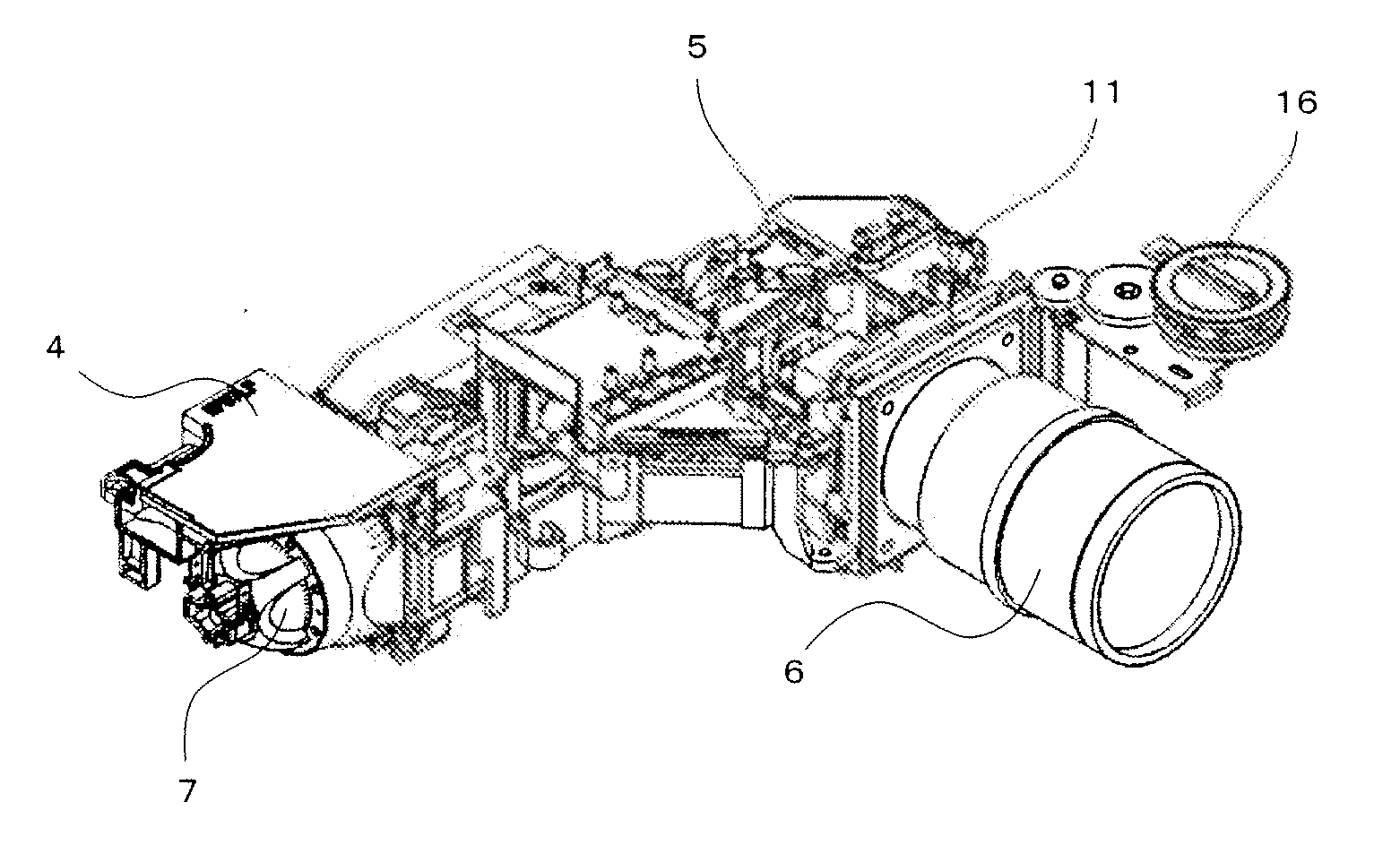
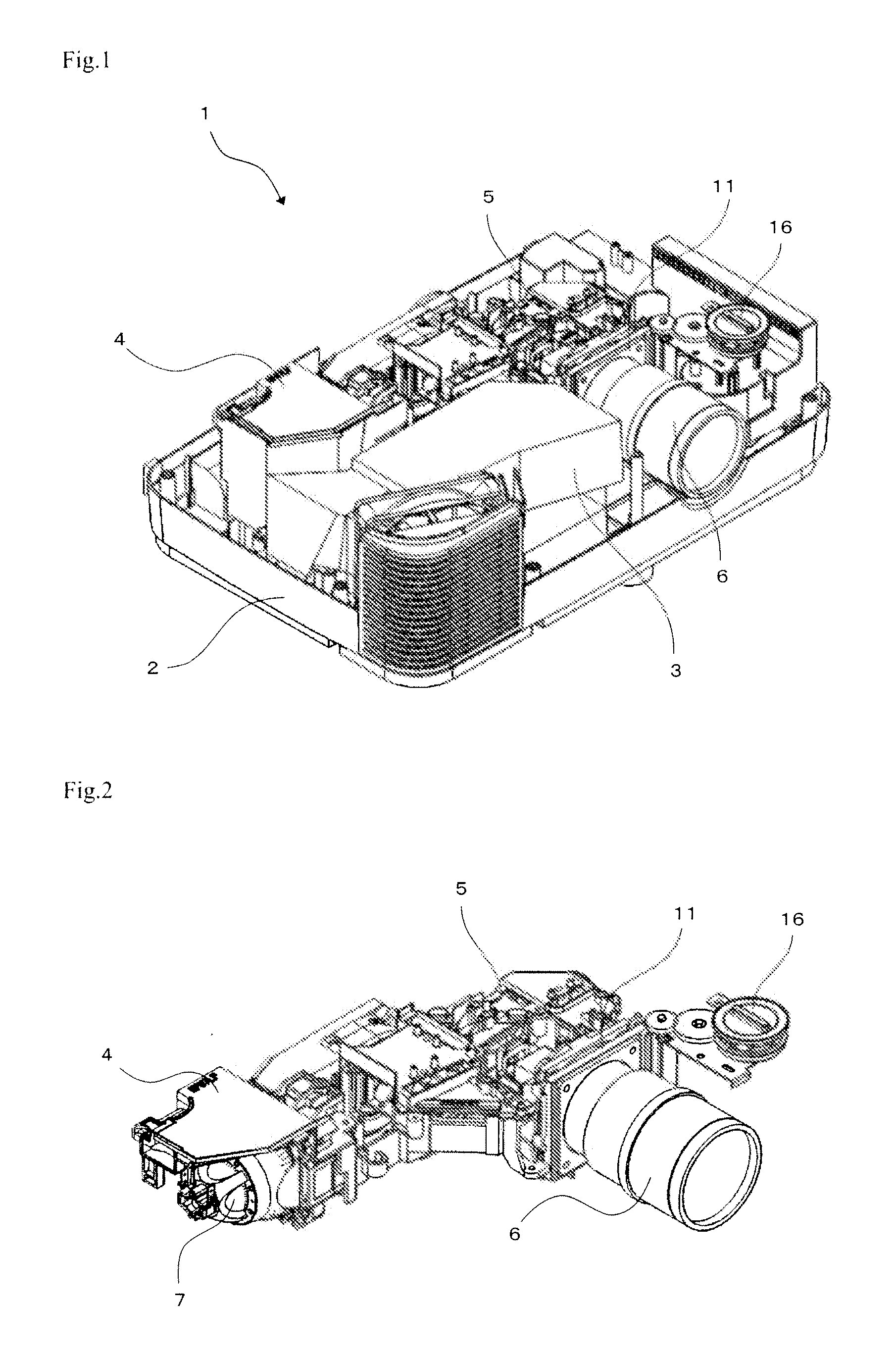
[0029]FIG. 1 is a perspective view showing the inside of projection display device 1 according to the exemplary embodiment of the present invention. As shown in FIG. 1, projection display device 1 includes, in lower case 2, power supply unit 3, lamp unit 4, optical engine 5, and projection lens 6. Projection display device 1, in which an internal electronic circuit board (not shown) is mounted, is used in the combined state of lower case 2 and an upper case (not shown).

[0030]Power supply unit 3 can supply power captured from the outside of projection display device 1 to lamp unit 4 or the internal electronic circuit board. As shown in FIG. 2, lamp unit 4 includes lamp 7 that emits white light. FIG. 2 is an enlarged perspective view of lamp unit 4, optical engine 5, and projection lens 6 shown in FIG. 1.

[0031]Optical engine 5 divides the white light into R (red), G (...


PUM


Abstract

Provided is a lens shifting device that has a simple structure and a small number of components, is compact and lightweight, and has high positional accuracy and slidability. The lens shifting device includes: first plate (12) through which video light passes; second plate (13) connected to first plate (12) via elastic member (23) and having projection lens (6) attached to a position into which the video light that passed through first plate (12) enters; slider (27) disposed to project from second plate (13) and housed in first plate (12) to be movable in a predetermined direction; and guide shaft (14) attached to first plate (12) in the state of being engaged with slider (27) and rotated to move the second plate. Elastic member (23) is disposed between first plate (12) and second plate (13) to connect first plate (12) and second plate (13) in the state of generating an elastic contraction force.

Description

TECHNICAL FIELD[0001]The present invention relates to a lens shifting device for moving a projection lens, and a projection display device including the same.BACKGROUND ART[0002]The projection display device includes an optical unit that generates a video according to a video signal, and a projection lens for magnifying and projecting the video.[0003]Recently, the projection display device further includes a lens shifting device that moves the projection lens in a predetermined direction intersecting an optical axis (hereinafter, referred to as video optical axis) where the projected video generated by the optical unit advances. Moving the projection lens enables movement of the projected video on a screen without moving the projection display device and reduction of formation of the projected video into a trapezoidal shape.[0004]By keeping constant the angle between the video optical axis and the center axis of the projection lens during movement of the projection lens, the video i...

Claims


Application Information

Patent Timeline
Patent Type & Authority Applications(United States)
IPC IPC(8): G03B21/14
CPCG03B5/04G03B21/147G03B21/145
Inventor FURUICHI, KUNITAKAOKADA, TAKAYUKI
Owner SHARP NEC DISPLAY SOLUTIONS LTD
Why Eureka
Try Eureka