Vehicle-side connector

a technology of side connector and vehicle, which is applied in the direction of connection contact member material, coupling device connection, transportation and packaging, etc., can solve the problem of creating pressure difference between the inside of the vehicle and the housing

Inactive Publication Date: 2012-11-22
SUMITOMO WIRING SYST LTD
View PDF11 Cites 55 Cited by
  • Summary
  • Abstract
  • Description
  • Claims
  • Application Information

AI Technical Summary

Benefits of technology

[0008]According to this configuration, it is possible to form the sealed space in the second tube, bring liquid in this sealed space to the drain port by the liquid guide and drain the liquid to the outside of the vehicle from the drain port by mounting the resilient to the second tube. Further, the sealed space communicates with the atmosphere through the drain port. Thus, the reverse flow of liquid or water from the drain port into the sealed space can be prevented regardless of a pressure variation inside the vehicle.
[0012]The resilient plug may include a base plate formed with at least one seal hole through which the wire is inserted in a sealed state. Thus, the resilient plug can be fixed more easily by arranging the base plate of the resilient plug between the retainer and the plug holder.
[0015]A long fluid guide would have to be formed from the opening of the outer tube to the mounting plate if the fluid guide was provided only in the outer tube without providing the resilient plug with the peripheral wall. As a result, the position of the drain port would be farther down and away from the inner tube and the mounting plate would become longer in a downward direction. However, the resilient plug of the invention is provided with the tapered peripheral wall and the fluid guide has the peripheral wall to the outer tube. As a result, the fluid guide in the outer tube can be made shorter. Accordingly, the position of the drain port can be located more upward (closer to the inner tube) and the mounting plate can be made shorter in a vertical direction.
[0016]Forward and backward movements of the resilient plug may be prevented by mounting the base plate between the retainer and the plug holder in forward and backward directions without forming any clearance.

Problems solved by technology

Further, a pressure difference is created between the inside of the vehicle and the housing chamber, and the water in the drain hose may flow back to the housing chamber due to this pressure difference.

Method used


Image

  • Vehicle-side connector
  • Vehicle-side connector
  • Vehicle-side connector

Examples


Embodiment Construction

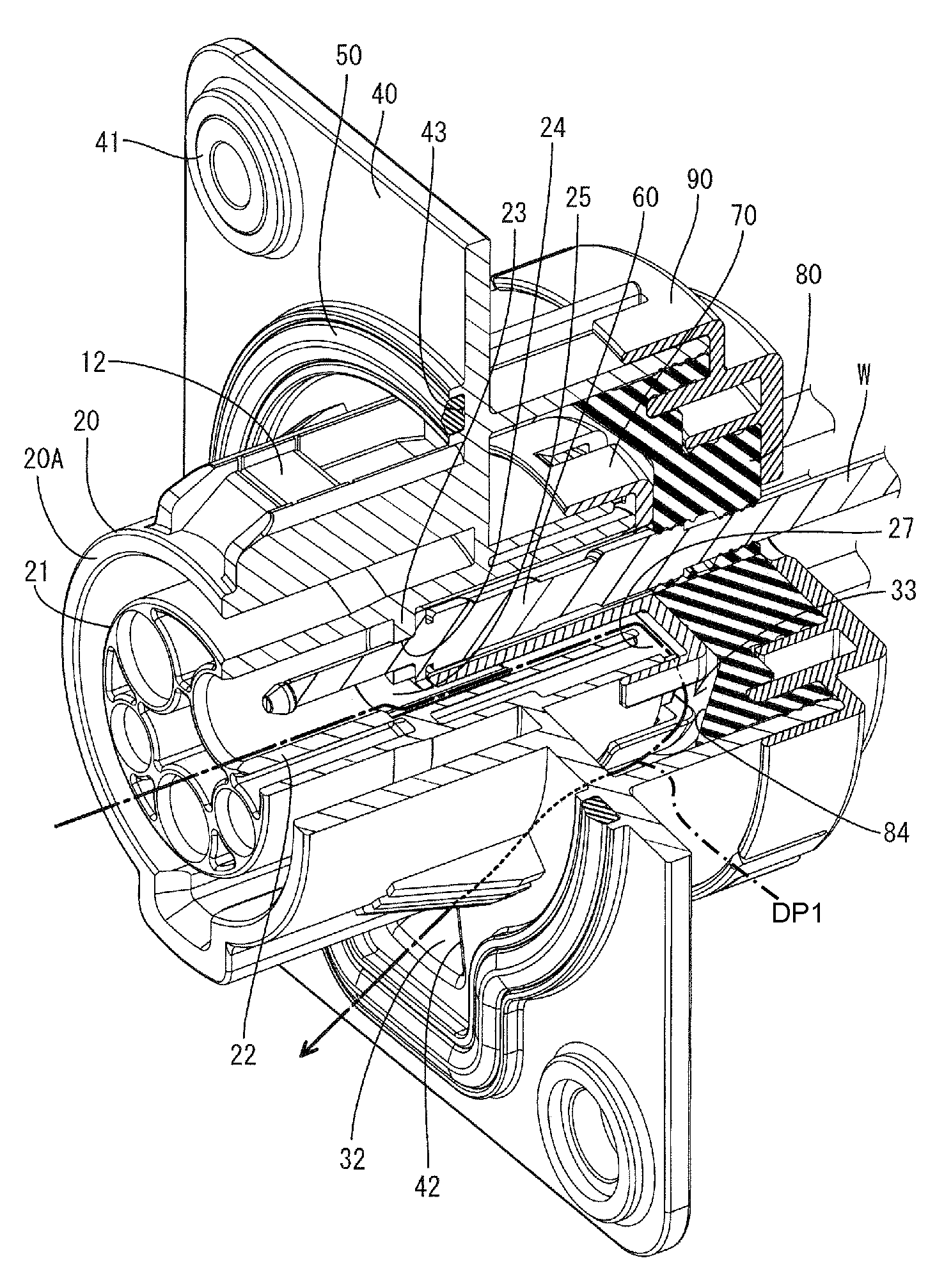
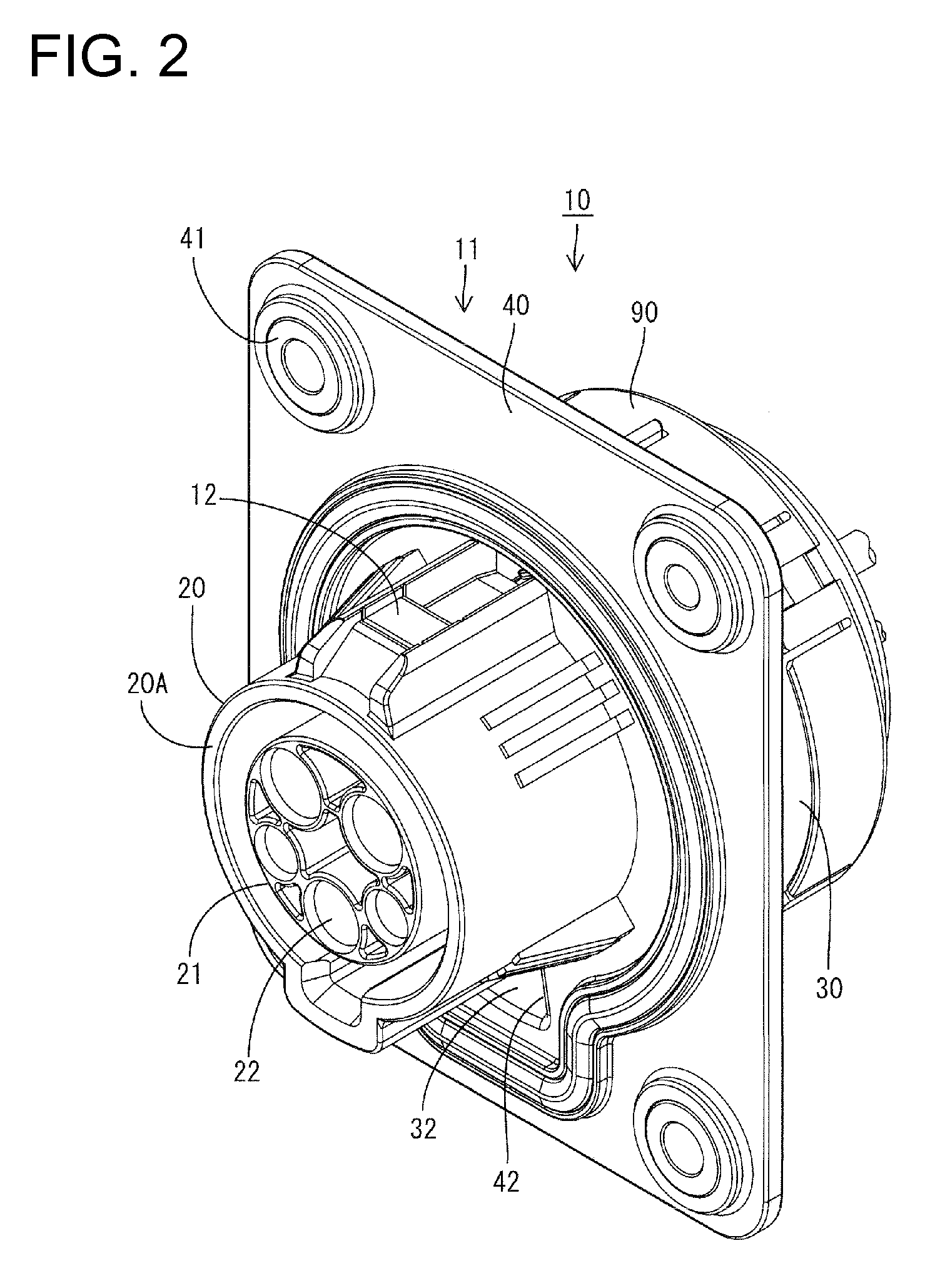
[0040]An embodiment of the invention is described with reference to FIGS. 1 to 20. A vehicle-side connector 10 in this embodiment is to be connected to a battery (not shown) installed in an electric vehicle, a hybrid vehicle or the like, and is connected to a charging connector (not shown) at the time of charging into the battery. As shown in FIG. 5, the vehicle-side connector 10 includes a housing 11 to be fastened to a body part, such as an outer panel P of the vehicle, by one or more bolts B1. A mounting hole B2 is formed in the outer panel P and the housing 11 is to be mounted and fixed to the outer panel P through this mounting hole B2.

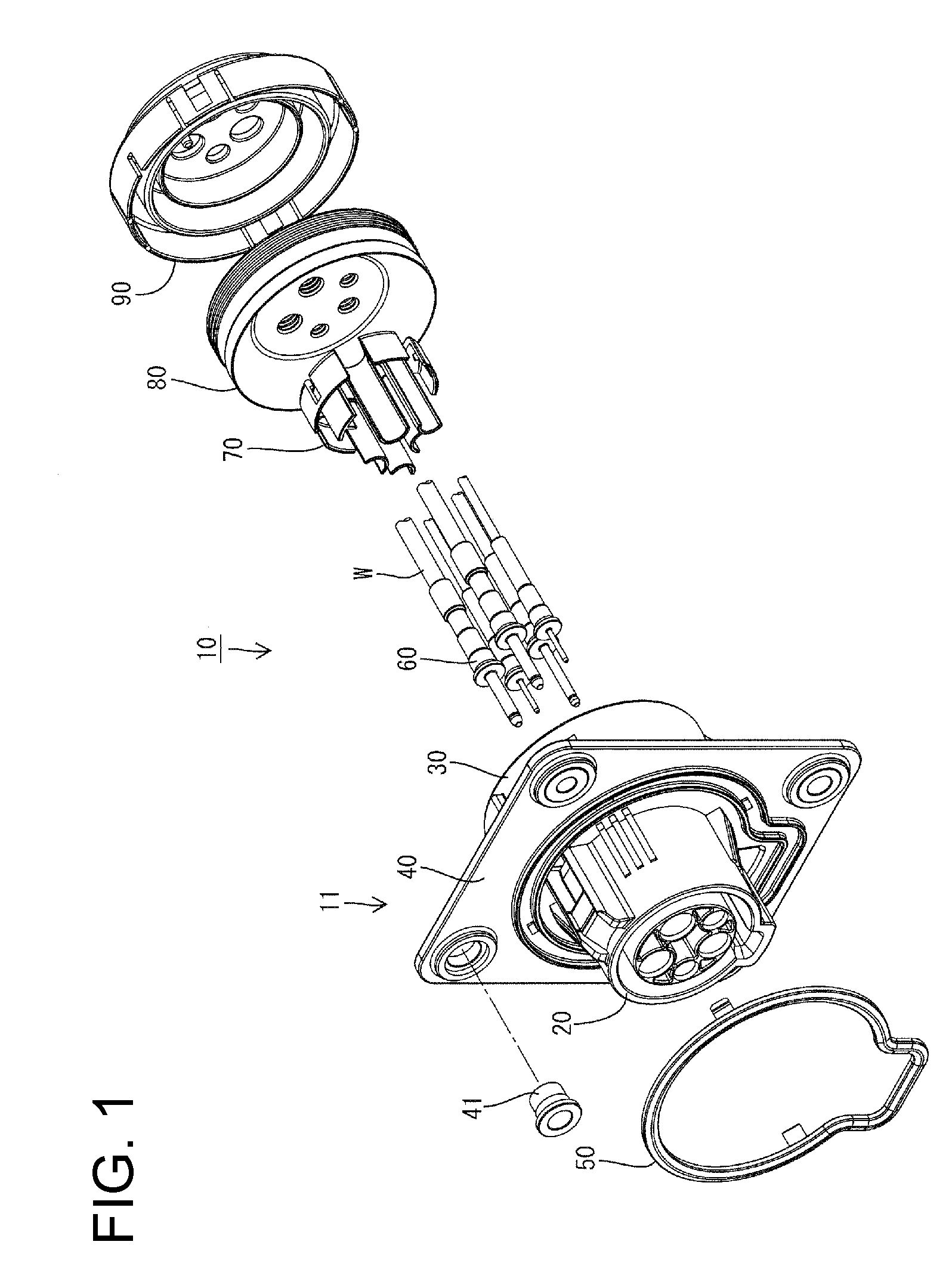
[0041]As shown in FIG. 1, the vehicle-side connector 10 includes the housing 11, a rubber ring 50 to be mounted on the front end of the housing 11, terminal fittings 60 to be accommodated in the housing 11, a retainer 70 to be mounted on rear end the housing 11, a rubber plug 80 to be mounted on the back side of the retainer 70 and a rubber plug ...


PUM


Abstract

A vehicle-side connector (10) includes a mounting plate (40) fixed to an outer panel (P) of a vehicle. An inner tube (20) penetrates the mounting plate (40). An outer tube (30) surrounds the inner tube (20) and projects from the mounting plate (40) toward the inside of the vehicle. A rubber plug (80) forms a sealed space (33) in the outer tube (30) between wires (W) pulled into the vehicle. A plug presser (90) is mounted in the opening of the outer tube (30) to retain the rubber plug (80). An inclined surface (84) is provided in the sealed space (33) and inclines down toward the outside of the vehicle. A drain channel (32) and a drain port (42) penetrate though the mounting plate (40) and drain water from the drain channel (32) to the outside of the vehicle.

Description

BACKGROUND OF THE INVENTION[0001]1. Field of the Invention[0002]The invention relates to a vehicle-side connector to be connected to a charging connector at the time of charging.[0003]2. Description of the Related Art[0004]U.S. Pat. No. 5,816,643 discloses a vehicle-side connector to be connected to a charging connector at the time of charging. The vehicle has a body and a housing chamber is provided in the body to face the outside of the vehicle. The vehicle-side connector is housed in the housing chamber. A tapered water guide is provided on the lower surface of the housing chamber and inclines down toward the outside of the vehicle. A downwardly open drain port is provided at a lower end of the water guide and a drain hose is connected to the drain port. Water that enters the housing chamber flows along the water guide and the drain port to the drain hose and is drained to a side below the housing chamber from the drain hose.[0005]However, the drain port is arranged in the housin...

Claims


Application Information

Patent Timeline
Patent Type & Authority Applications(United States)
IPC IPC(8): H01R4/60
CPCH01R13/5208H01R13/5227H01R13/74Y02T90/14H01R43/005B60L11/1818Y02T10/7005H01R2201/26B60L53/16Y02T10/70Y02T10/7072
Inventor ICHIO, TOSHIFUMITAKADA, AKINORI
Owner SUMITOMO WIRING SYST LTD
Why Eureka
Try Eureka