
Method and system for identifying leaks in liquid pipe construction

a technology for liquid pipes and leaks, applied in the direction of liquid/fluent solid measurement, volume measurement, volume measurement, etc., can solve the problem that the solution cannot be used to detect real-time fluid leaks in pipe construction

Inactive Publication Date: 2012-11-22
NLEAK
View PDF7 Cites 58 Cited by
  • Summary
  • Abstract
  • Description
  • Claims
  • Application Information

AI Technical Summary

Benefits of technology

[0015]According to some embodiments of the present invention the sound recognition algorithm is programmed to identify sounds signals related to water flow including “dripping” sounds at predefined distance and filtering out background noise.
[0016]According to some embodiments of the present invention the detection unit has a unique identifier code enabling the control unit to identify irregular flow at specific controlled exit point enabling quantitative data analysis of liquid flow in the pipe construction.

Problems solved by technology

The various leak detection methods described above use acoustic sensors located within the pipes, requiring complicated algorithm for identifying leak along the pipe, such solution may not be use to detect real time fluid leak within pipe construction for immediate activation of shutoff valve.

Method used


Image

  • Method and system for identifying leaks in liquid pipe construction
  • Method and system for identifying leaks in liquid pipe construction
  • Method and system for identifying leaks in liquid pipe construction

Examples


Embodiment Construction

[0034]Before explaining at least one embodiment of the invention in detail, it is to be understood that the invention is not limited in its application to the details of construction and the arrangement of the components set forth in the following description or illustrated in the drawings. The invention is applicable to other embodiments or of being practiced or carried out in various ways. Also, it is to be understood that the phraseology and terminology employed herein is for the purpose of description and should not be regarded as limiting.

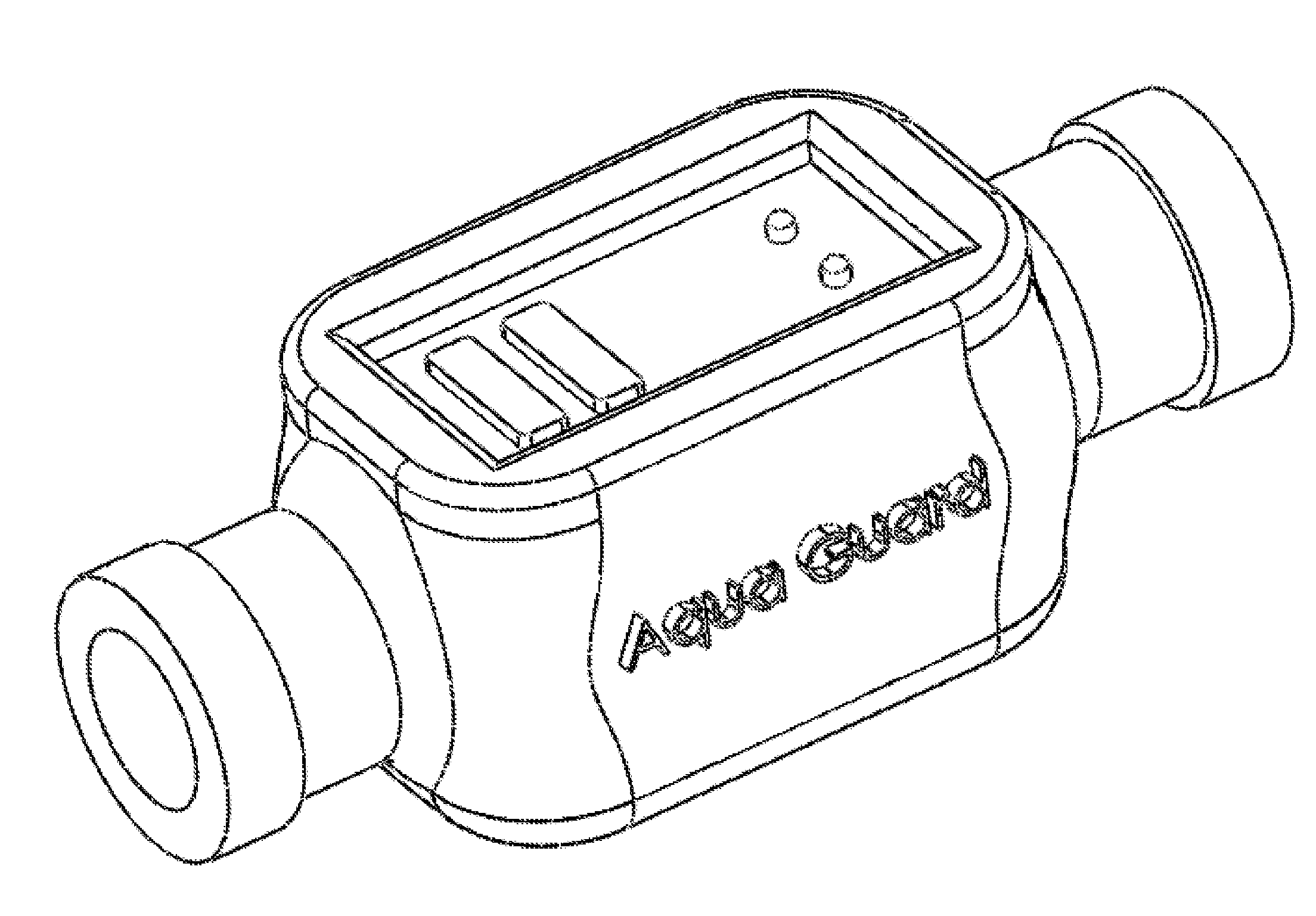
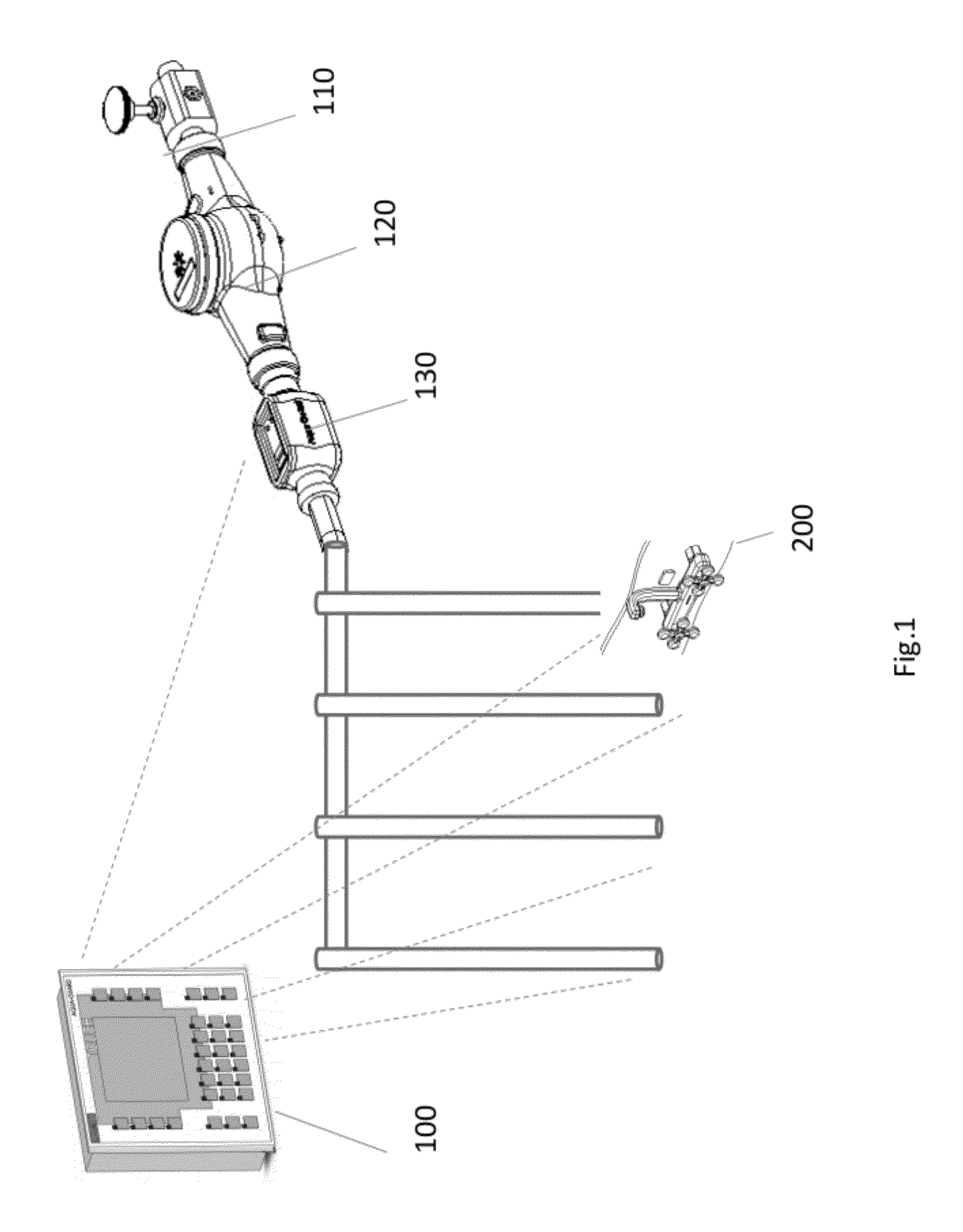
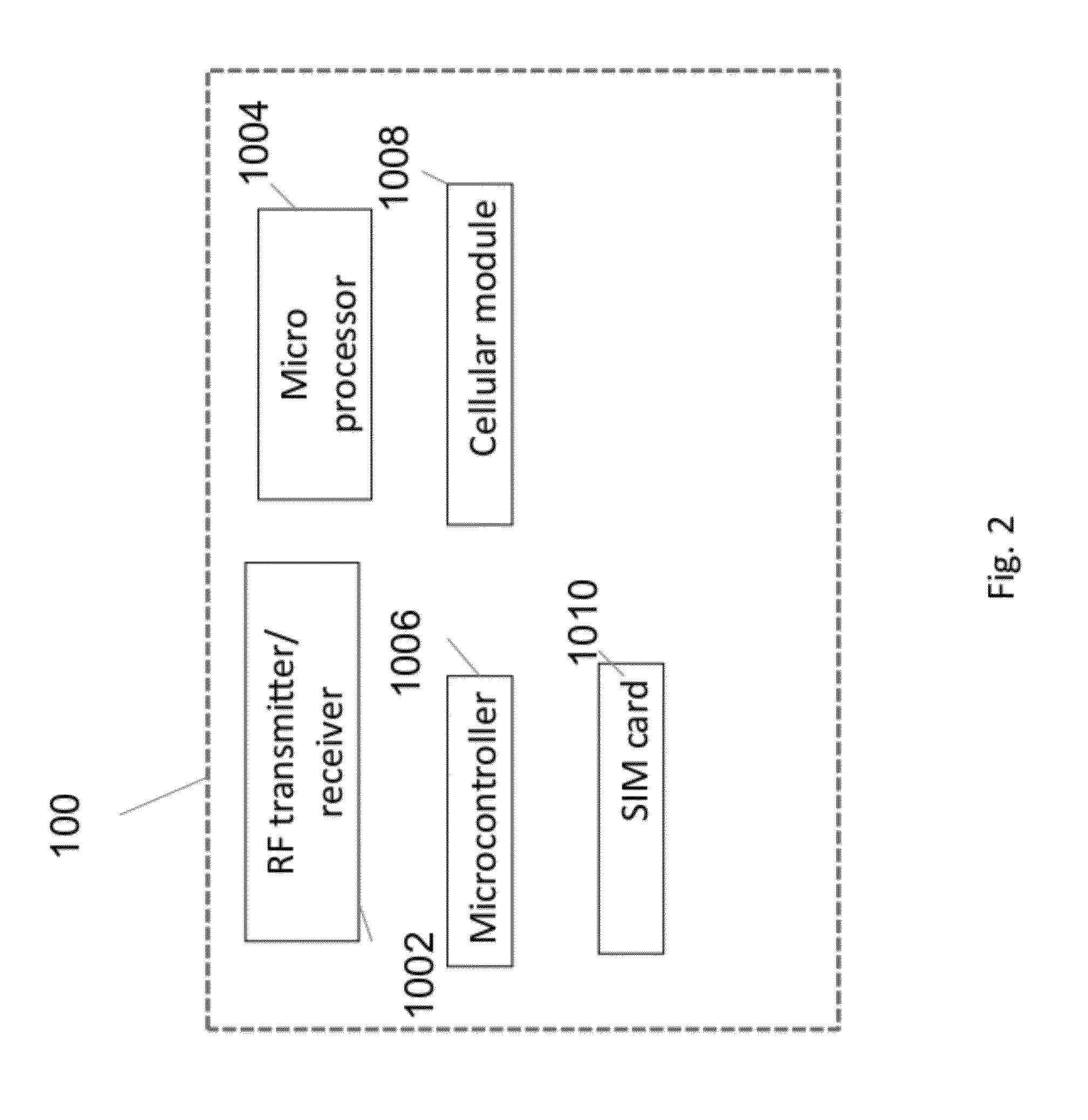
[0035]FIG. 1 illustrates the main components of the leak detection system implemented in pipe construction system according to the present invention. The system includes, a controller unit 100, entrances point valve 110, metering unit 112, shutoff unit 130 positioned at the entrance point and plurality of detection devices 140 positioned in proximity of controlled exit points of the pipe construction. The controller communicates through wirele...


PUM


Abstract

The present invention provides a system for identifying leaks in liquids pipe construction. The system is comprised of: At least one detection unit is positioned in proximity of at least one exit point of said pipe construction comprising an acoustic sensor and a wireless communication unit, an electronically controlled shutoff unit installed on an entrance point of the pipe construction, the unit comprising a valve, an acoustic sensor and wireless communication unit arranged for transmitting data of water flow and receiving control signals, a controller network device for receiving the measurement data from all sensors. The controller is programmed to detect leaks when identifying differences between the measured liquid flow at the entrance point and measured flow at the exit points.

Description

BACKGROUND[0001]1. Technical Field[0002]The present invention relates to the field of identification of liquids in pipes construction and more specifically to identification of leak by acoustical sensors.[0003]2. Prior Art[0004]There are known in the art various systems for leak detection: U.S. application No. US2006174707 disclose device for detecting and control abnormal flow occurrences in a liquid or gas-carrying infrastructure using acoustics sensors.[0005]U.S. Pat. No. 5,040,409 disclose an acoustic sensor to determine when a leak occurs in a sprinkling system. When a catastrophic leak is detected, an alarm signal is generated and a shutoff valve may be actuated in order to prevent loss of fluid and possible damage that can occur due to localized high flow of the fluid that is being sprayed. US2004128034 patent application disclose liquid flow detection using a microphone or other acoustic sensor to detect the acoustic signature of liquid flow through a pipe. Based on the anal...

Claims


Application Information

Patent Timeline
IPC IPC(8): G06F19/00
CPCG01M3/243G06F19/00F17D3/18F17D5/005F17D5/02G16Z99/00
Inventor BARKAY, DOV
Owner NLEAK
Learn More