Cooling arrangement for a chargeable internal combustion engine

a technology of internal combustion engine and cooling arrangement, which is applied in the direction of machines/engines, mechanical equipment, cylinders, etc., can solve the problems of affecting the economical efficiency of motor vehicles, circuit arrangement does not provide heating of charge air, and mixing of coolant from both coolant circuits is not possible, so as to reduce the oxygen proportion per volumetric unit, reduce the oxygen proportion, and reduce the power increase of the engine

Inactive Publication Date: 2012-11-29
FORD GLOBAL TECH LLC
View PDF7 Cites 44 Cited by
  • Summary
  • Abstract
  • Description
  • Claims
  • Application Information

AI Technical Summary

Benefits of technology

[0013]In doing so, the present disclosure provides an energy-efficient cooling arrangement for a chargeable internal combustion engine, which cooling arrangement especially shortens warming-up phases of the internal combustion engine and therefore allows a periodic raising of the charge-air temperature level within the shortest time, especially with regard to defined regeneration strategies of exhaust gas aftertreatment components, for example of diesel particulate filters. The cooling arrangement which is to be disclosed, moreover, is to be simply designed with respect to control engineering and is also to enable a short-term reaction to changes of the operating parameters of the internal combustion engine, of a downstream exhaust gas aftertreatment system and / or of the state variables in the cooling circuits.
[0014]The features which are individually explained in the following description can be combined with each other in any technically expedient manner and disclose further developments of the disclosure. The description characterizes and specifies the disclosure especially in conjunction with the figures in addition.
[0016]It should be understood that the summary above is provided to introduce in simplified form a selection of concepts that are further described in the detailed description. It is not meant to identify key or essential features of the claimed subject matter, the scope of which is defined uniquely by the claims that follow the detailed description. Furthermore, the claimed subject matter is not limited to implementations that solve any disadvantages noted above or in any part of this disclosure.

Problems solved by technology

The higher fuel consumption which is caused by this, however, impairs the economical efficiency of the motor vehicle.
The disclosed circuit arrangement does not provide heating of the charge air.
A main cooling circuit for cooling the engine is provided separately from the low-temperature cooling circuit so that mixing of the coolant from both coolant circuits is not possible.
For example, in the case of two separate cooling circuits for charge-air cooling and for cooling an internal combustion engine in each case, the arrangements do not allow a short-term raising of the charge-air temperature level, and, on the other hand, in the case of two interconnectable cooling circuits, lead to mixing of the coolant of the two circuits, that is to say the low-temperature circuit and the high-temperature circuit or the engine cooling circuit.
As a result of this, the heating process of the coolant from the engine cooling circuit is delayed on account of a greater thermal mass for the engine cooling circuit which consequently extends the warming-up phases of the internal combustion engine.
Furthermore, mixing of hot coolant from the engine cooling circuit with the coolant of the low-temperature circuit has a disadvantageous effect with regard to an achievable minimum temperature in the low-temperature circuit.

Method used


Image

  • Cooling arrangement for a chargeable internal combustion engine
  • Cooling arrangement for a chargeable internal combustion engine
  • Cooling arrangement for a chargeable internal combustion engine

Examples


Embodiment Construction

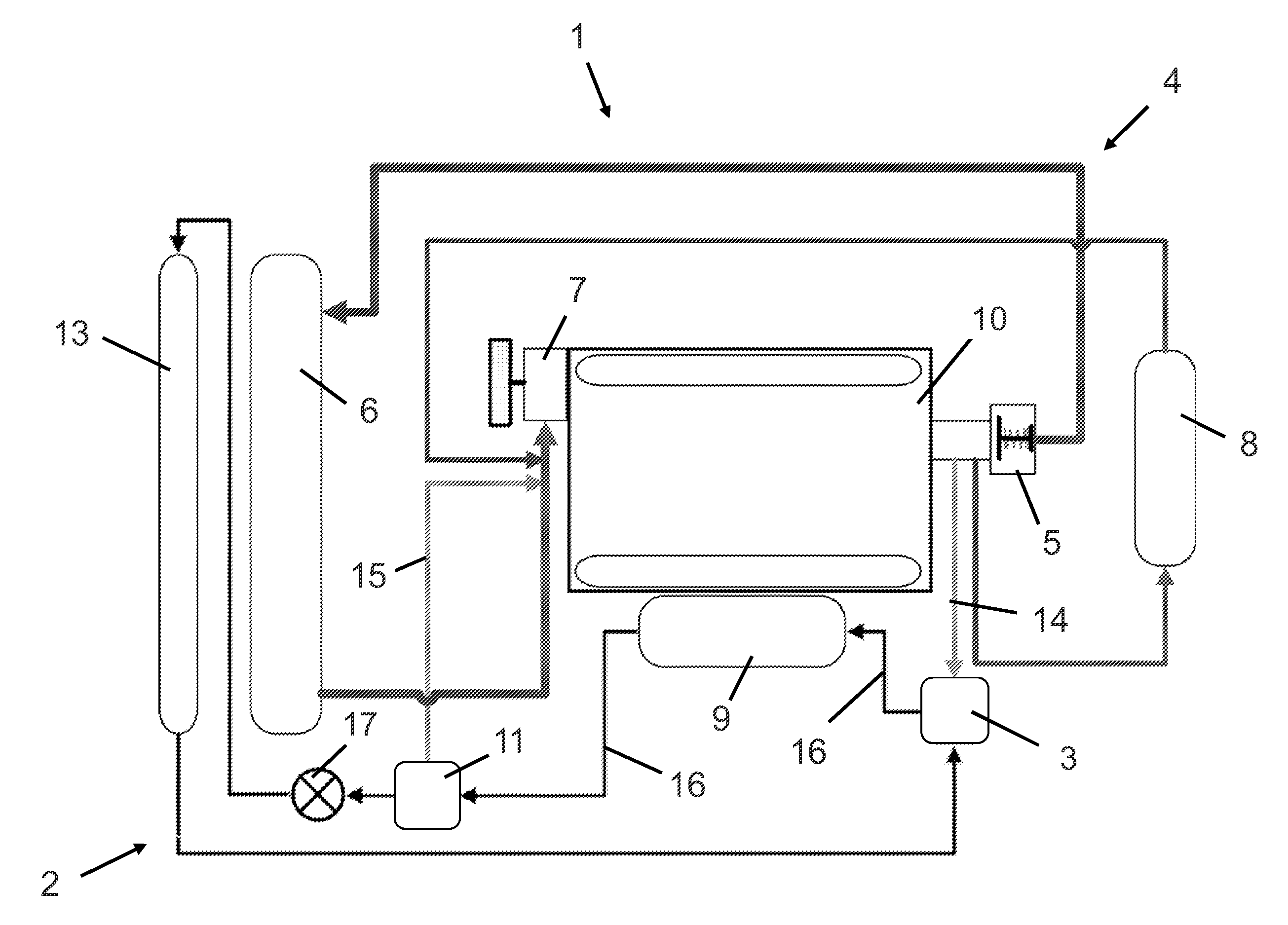
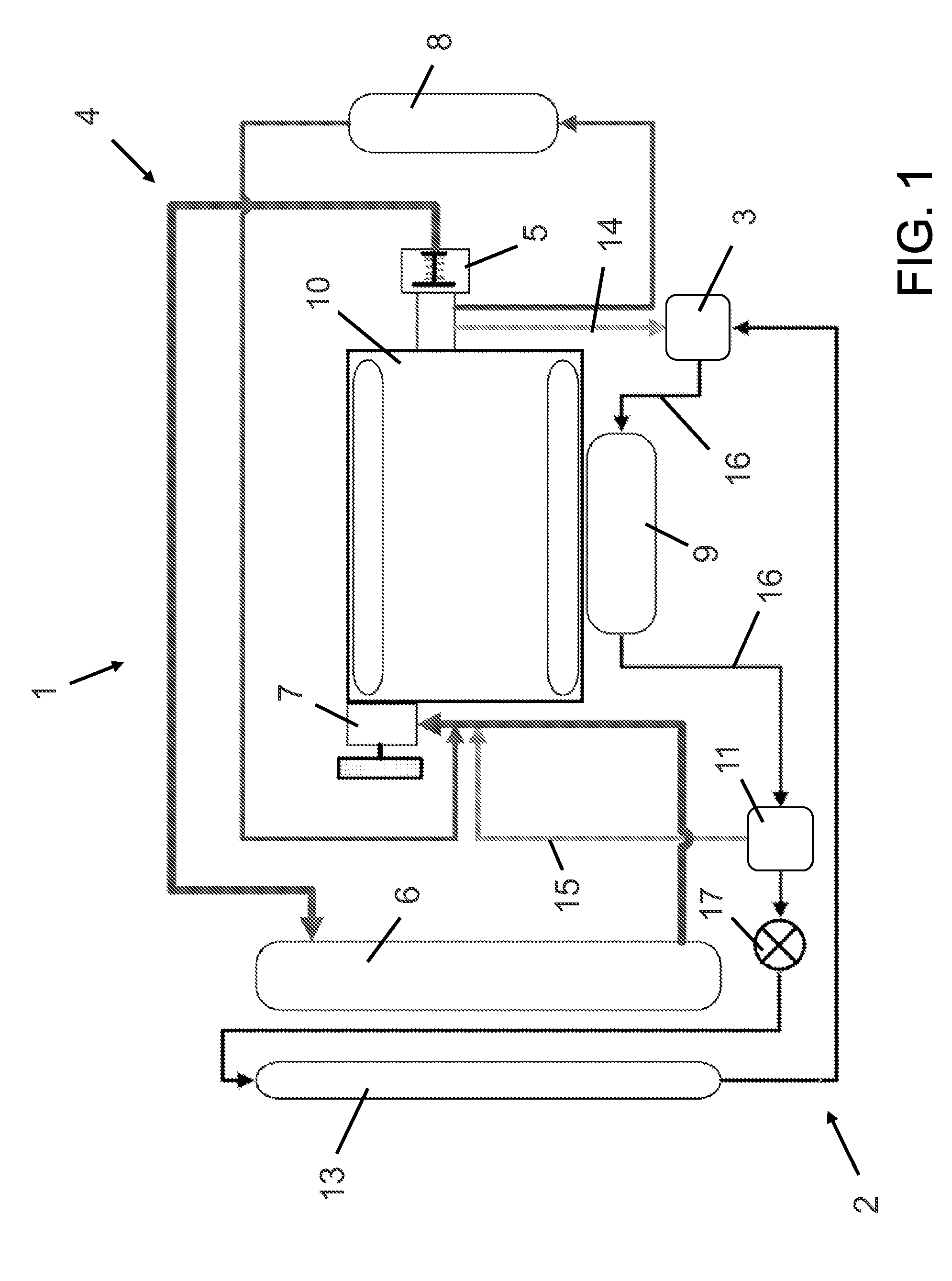
[0020]According to the disclosure, a cooling arrangement comprises a low-temperature circuit for charge-air cooling of a turbocharger of an internal combustion engine, especially of a diesel engine, and an engine cooling circuit for cooling the internal combustion engine, wherein a charge-air cooler, which is arranged in the low-temperature circuit, can be connected in a fluid-conducting manner on the coolant inlet side, via a first valve device, and on the coolant outlet side, via a second valve device, to the low-temperature circuit or to the engine cooling circuit.

[0021]Accordingly, when required, that is to say if, for example, heating of the charge air is desired and the coolant temperature in the engine cooling circuit exceeds the charge-air temperature after compression by the turbocharger, the charge-air cooler can be integrated directly into the engine cooling circuit via the first and second valve devices. Therefore, on the one hand, the energy which is present in the engi...


PUM


Abstract

Embodiments for a cooling arrangement are provided. In one example, a cooling arrangement comprises a low-temperature circuit for charge-air cooling of a turbocharger of an internal combustion engine, an engine cooling circuit for cooling the internal combustion engine, and a charge-air cooler arranged in the low-temperature circuit and connected in a fluid-conducting manner on a coolant inlet side, via a first valve device, to the low-temperature circuit and to the engine cooling circuit, and on a coolant outlet side, via a second valve device, to the low-temperature circuit and to the engine cooling circuit. In this way, coolant from the engine may heat the charge-air cooler under certain conditions.

Description

RELATED APPLICATIONS[0001]The present application claims priority to German Patent Application Number 102011076457.7, filed on May 25, 2011, the entire contents of which are hereby incorporated by reference for all purposes.FIELD[0002]The present disclosure refers to a cooling arrangement for a chargeable internal combustion engine.BACKGROUND AND SUMMARY[0003]Cooling arrangements are used, for example, in internal combustion engines, especially motor vehicle engines, with turbochargers in order to cool the internal combustion engine, using the engine cooling circuit, and to cool the charge air—which is fed to the internal combustion engine via the turbocharger—using the low-temperature cooling circuit.[0004]Modern chargeable internal combustion engines, especially chargeable diesel engines, customarily have a charge-air cooling system by means of which the air which is required for charging the internal combustion engine is cooled. A charge-air cooling system in this case is require...

Claims


Application Information

Patent Timeline
Patent Type & Authority Applications(United States)
IPC IPC(8): F02B29/04F01P7/00
CPCF01P3/20F02B29/0475F01P2060/02F01P7/165
Inventor VIGILD, CHRISTIAN WINGEQUIX, HANS GUENTER
Owner FORD GLOBAL TECH LLC
Why Eureka
Try Eureka