Method of checking a membrane filtration module of a filtration plant

Inactive Publication Date: 2012-11-29
KRONES AG
View PDF8 Cites 5 Cited by
  • Summary
  • Abstract
  • Description
  • Claims
  • Application Information

AI Technical Summary

Benefits of technology

[0014]By introducing compressed air into the discharge pipe, it is possible to carry out a test method similar to the bubble point method in the installed state of the membrane filtration module. By this, the integrity of the membrane filtration module can be reliably checked in a simplified manner.
[0023]The membrane filtration module can remain in the filtration plant for checking it. In other words, the steps of the method of checking the integrity of the membrane filtration module, in particular the membrane element, can be carried out with the membrane filtration module being installed. So, for checking the membrane filtration module, it does not have to be removed from the filtration plant. By this, the checking of the membrane filtration module can be clearly facilitated.
[0028]Moreover, the period between the beginning of the introduction of the compressed air and the occurrence of one or several air bubbles in the liquid can be determined. By this, additional information about a possible defect can be obtained in a simple manner.
[0029]The method can moreover comprise a determination or at least an assessment of a location of a defect of the membrane element based on the determined period. By this, a position of a possible defect can be determined or at least assessed in a simple manner.
[0040]In other words, the adapter can be used for performing an above-described method. Thereby, the adapter permits a simple and reliable check of a membrane filtration module of a filtration plant.

Problems solved by technology

The membranes often experience loads due to undesired pressure blows or too quickly changing temperature gradients in cleaning operations.
This can result in damages of the membrane or the connection between the potting and the membrane or housing, respectively.
In particular when plastic membranes are used, these can tear off or even burst directly at the transition to the potting.
It is a disadvantage of this method that it does not indicate what is defective in the membrane filtration module, i.e. a membrane or the potting, and neither the degree of the damage can be derived from it.
Moreover, it cannot be determined which membrane is defective at what position.
However, it is a disadvantage of this method that, due to the required removal of the membrane filtration module, it is very cumbersome and can lead to relatively long downtimes of the filtration plant.

Method used


Image

  • Method of checking a membrane filtration module of a filtration plant
  • Method of checking a membrane filtration module of a filtration plant
  • Method of checking a membrane filtration module of a filtration plant

Examples


Embodiment Construction

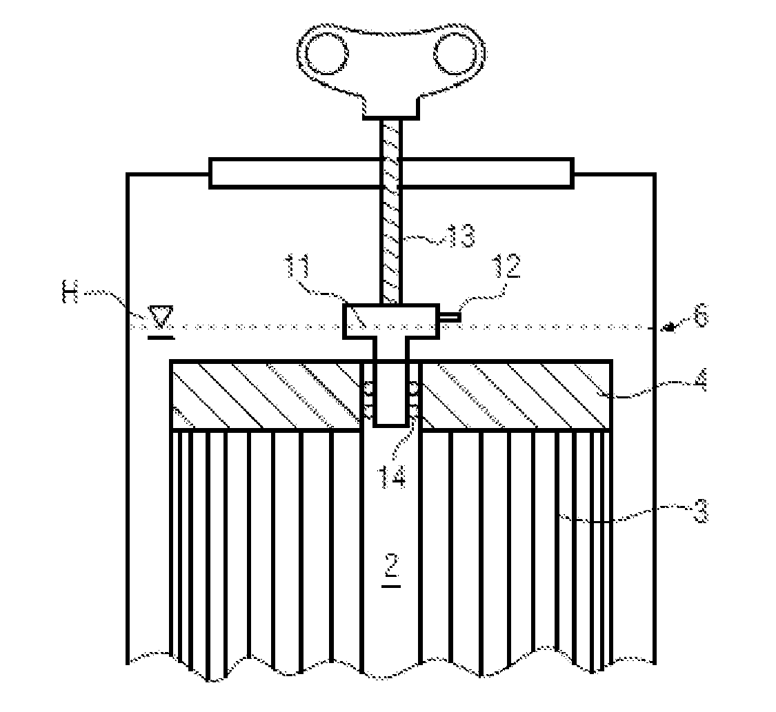
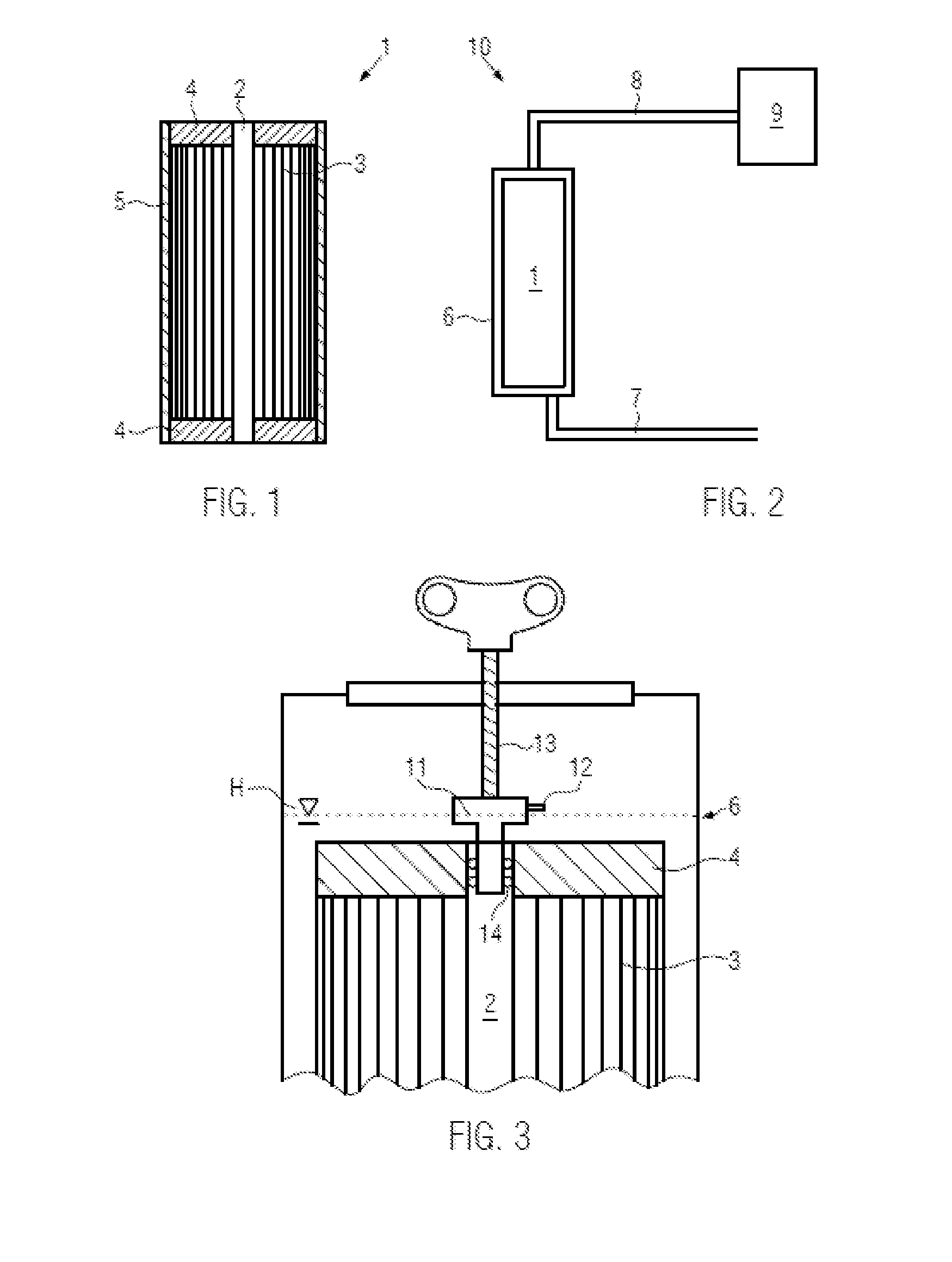
[0059]In FIG. 1, an exemplary membrane filtration module 1 with a central discharge pipe 2 is shown. Membrane filtration is employed, for example, in water treatment. These are usually ultrafiltration plants. The membrane filtration module shown in FIG. 1 is a so-called hollow fiber filtration module. In other words, the plastic membranes are embodied in the form of several hollow fibers 3. A membrane filtration module can comprise several hundred to several thousand hollow fiber membranes. For example, 1000 to 5000 hollow fiber membranes can be provided. The (mean) pore size of the membrane can be between 0.8 μm and 0.02 μm.

[0060]By a so-called potting 4, the hollow fiber membranes 3 are firmly connected or potted with a cartridge shell 5 at the upper and the lower end.

[0061]The exemplary membrane filtration module 1 of FIG. 1 moreover comprises a central discharge pipe 2. Via this discharge pipe 2, the filtrate can be discharged from the membrane filtration module 1.
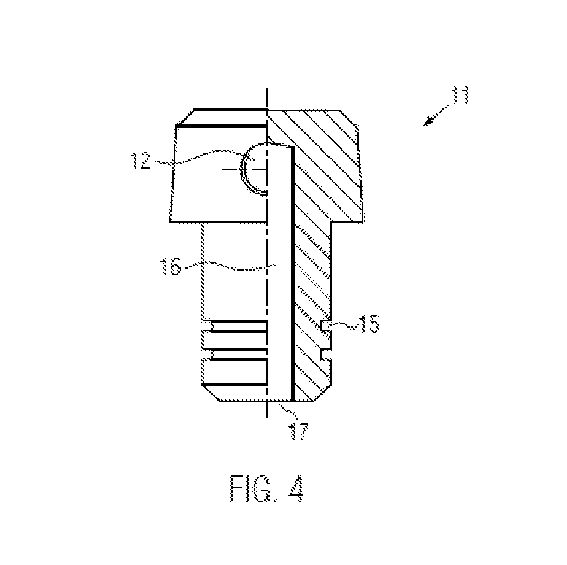
[0062]The disc...


PUM


Abstract

A method of checking a membrane filtration module of a filtration plant, where the membrane filtration module includes a discharge pipe for the filtrate and a membrane element for filtering a liquid, and includes filling the membrane filtration module with a liquid, so that the membrane element is completely immersed in the liquid, and introducing compressed air into the discharge pipe.

Description

CROSS-REFERENCE TO RELATED APPLICATION[0001]The present application claims the benefit of priority of German Application No. 102011006545.8, filed Mar. 31, 2011. The entire text of the priority application is incorporated herein by reference in its entirety.FIELD OF THE DISCLOSURE[0002]The present disclosure relates to a method of checking a membrane filtration module of a filtration plant, wherein the membrane filtration module comprises a discharge pipe for the filtrate, and also to an adapter for the connection with a discharge pipe of a membrane filtration module of a filtration plant.BACKGROUND[0003]Membrane filtration modules are employed, for example, in water treatment. These are usually ultrafiltration plants. Here, plastic membranes whose pore sizes are within a range of about 1 μm to 0.001 μm are employed. In some areas, ceramic membranes are also employed.[0004]A frequent structural shape of membrane filtration modules comprises a central discharge pipe surrounded by the...

Claims


Application Information

Patent Timeline
IPC IPC(8): G01N15/08F16L21/035
CPCB01D63/02B01D65/102B01D65/104B01D2315/06B01D2313/13B01D2313/243G01N15/082
Inventor MAYR, STEPHANZACHARIAS, JORG
Owner KRONES AG
Why Eureka
Try Eureka