Radar level gauge and methods of testing radar level gauge and system

a level gauge and level gauge technology, applied in the direction of instruments, machines/engines, using reradiation, etc., can solve the problems of increased risk of potentially dangerous overfill conditions, time-consuming and laborious procedures, and increased risk of overfill conditions

Active Publication Date: 2015-01-08
ROSEMOUNT TANK RADAR
View PDF7 Cites 10 Cited by
  • Summary
  • Abstract
  • Description
  • Claims
  • Application Information

AI Technical Summary

Benefits of technology

[0043]To provide for a reliable proof test with a minimum of manual intervention, the reference reflector may advantageously be arranged and configured substantially identically in the filling level measuring state and in the proof test state.
[0044]In various embodiments of the radar level gauge according to the present invention, the reference reflector may advantageously be attached to the propagation device. Through this configuration, a suitable reference reflector echo can be provided without the need for additional through-holes through the tank roof etc.

Problems solved by technology

Radar level gauges are in some cases used for applications where malfunction of the radar level gauge could result in dangerous situations.
This procedure may take quite a lot of time and requires personnel to be involved in pumping and measuring.
Furthermore, deliberately raising the level of product in the tank to a high level may actually involve an increased risk for a potentially dangerous overfill condition.

Method used


Image

  • Radar level gauge and methods of testing radar level gauge and system
  • Radar level gauge and methods of testing radar level gauge and system
  • Radar level gauge and methods of testing radar level gauge and system

Examples


first embodiment

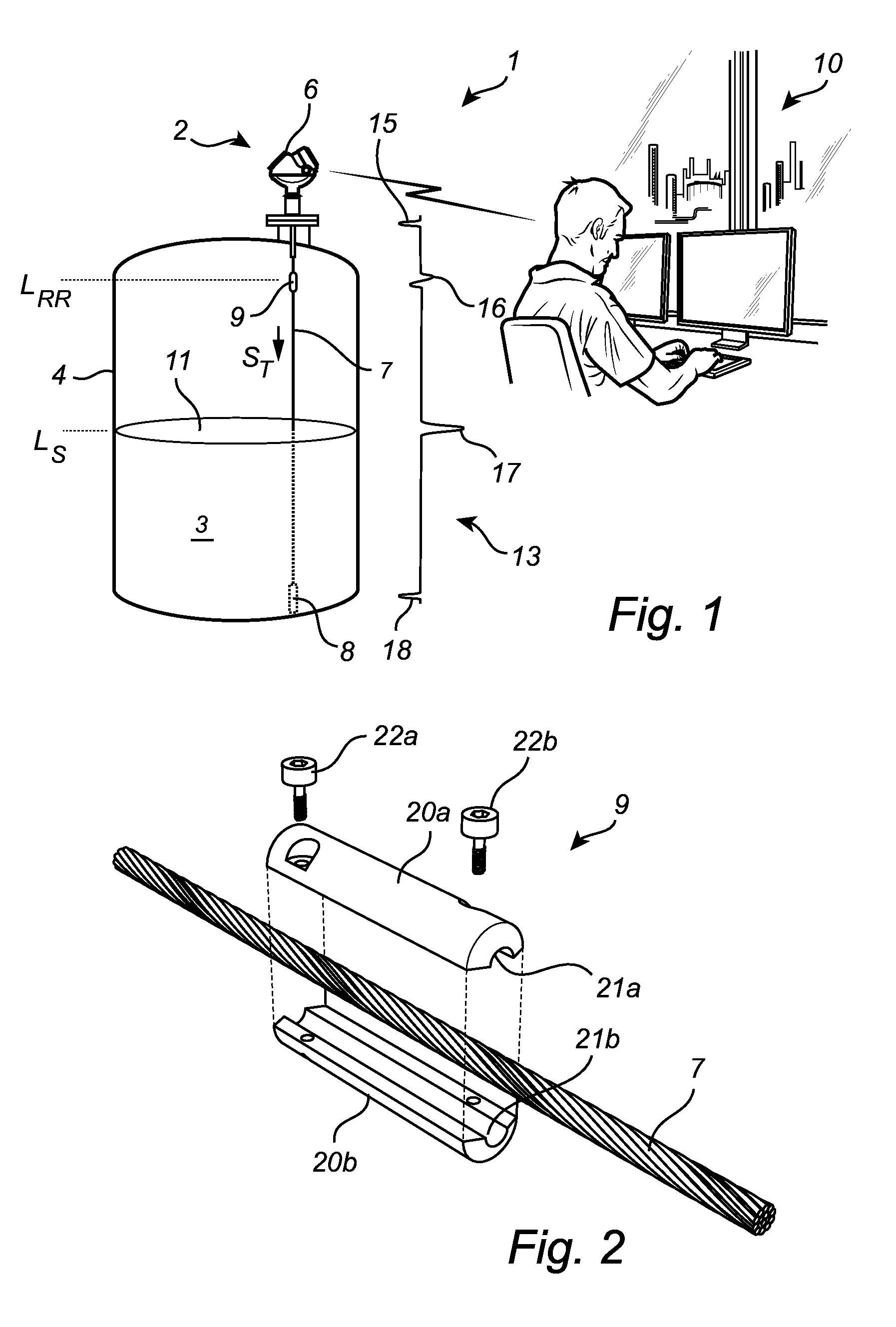
[0068]FIG. 1 schematically shows a level measuring system 1 according to the present invention. The level measuring device 1 in FIG. 1 comprises a radar level gauge 2 of GWR (Guided Wave Radar) type and a host system 10 illustrated as a control room.

[0069]The radar level gauge 2 is installed to measure the filling level of a product 3 contained in a tank 4. The radar level gauge 2 comprises a measuring unit 6 and a propagation device in the form of a transmission line probe 7 extending from the measuring unit 6 towards and into the product 3. In the example embodiment in FIG. 1, the transmission line probe 7 is a single lead wire probe, that has a weight 8 attached at the end thereof to keep the wire probe straight and vertical. The radar level gauge 2 further comprises a reference reflector 9 attached to the transmission line probe 7 at a reference reflector level LRR.

[0070]The measurement unit 6 comprises (not shown in FIG. 1) a transceiver, processing circuitry and a communicatio...

second embodiment

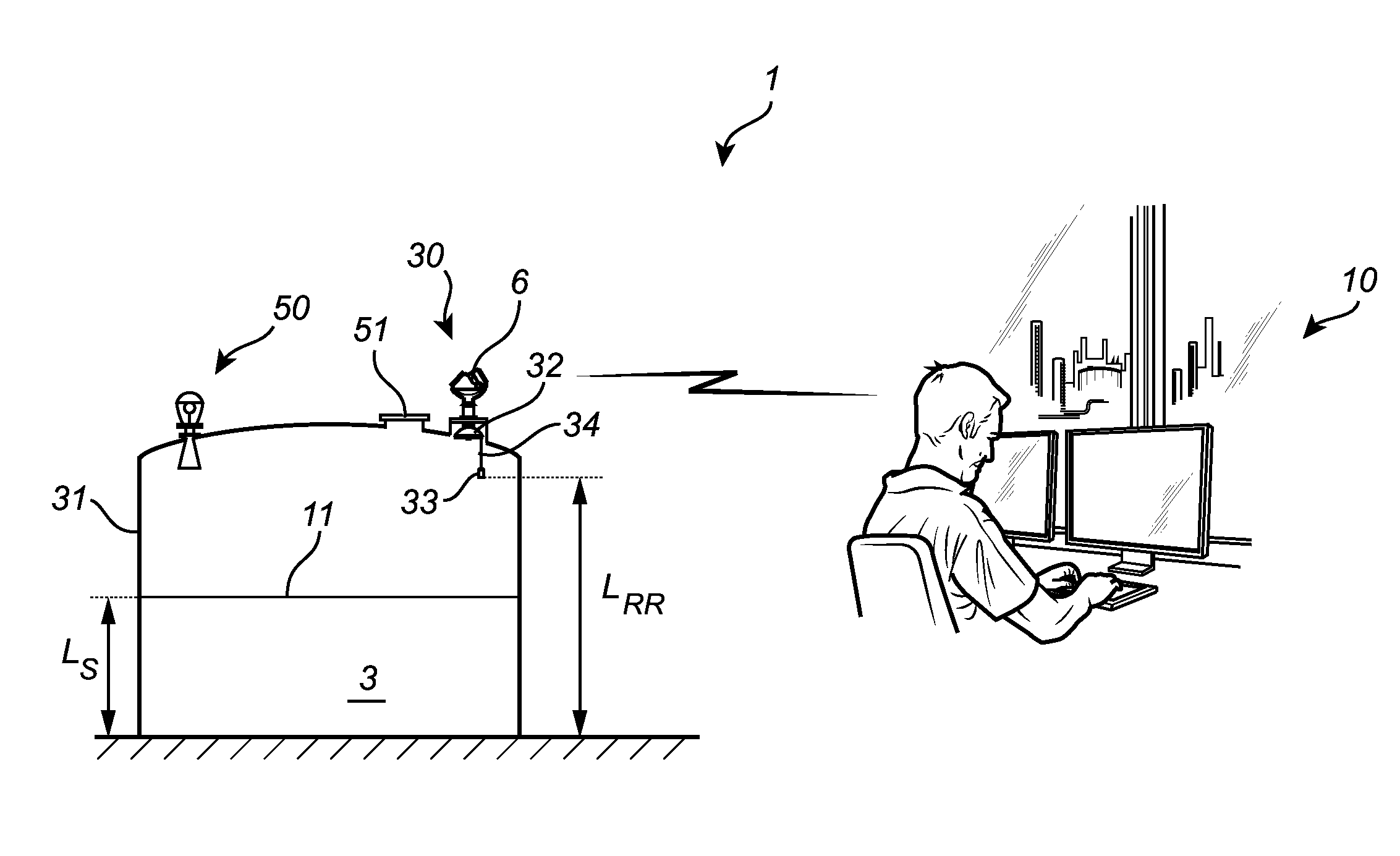
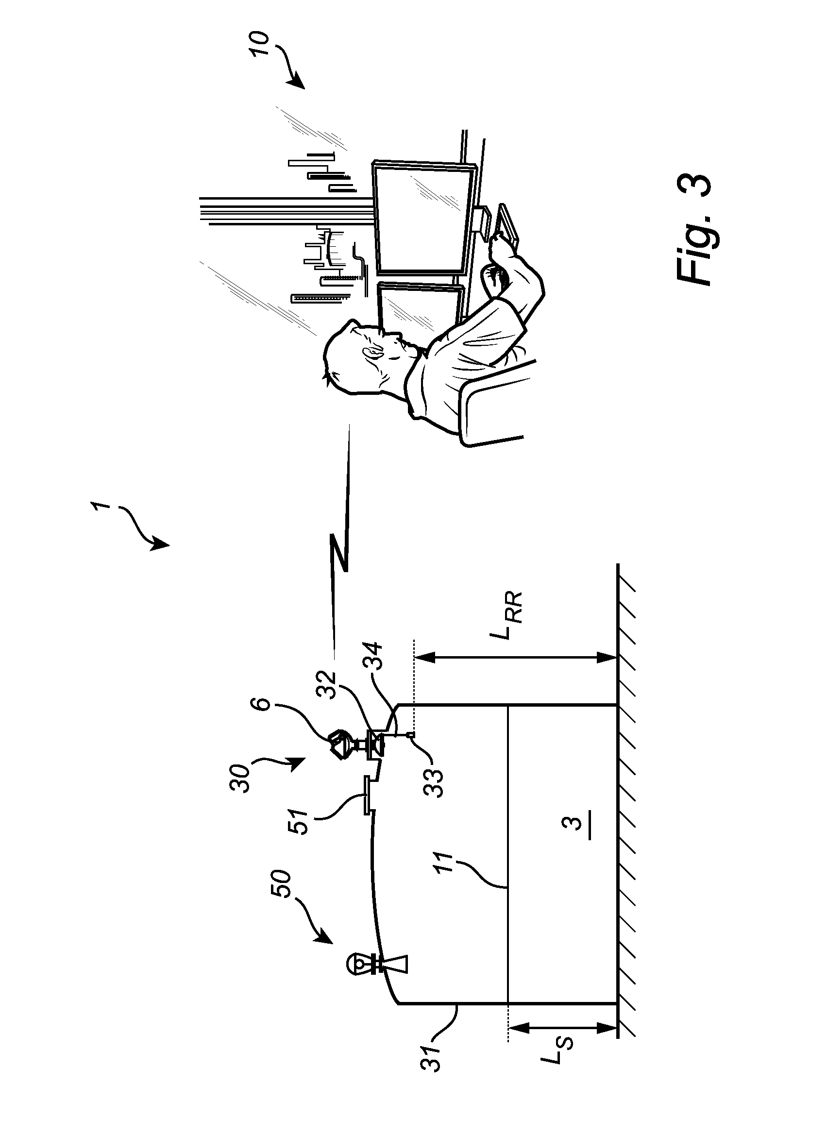
[0078]the filling level measuring system 1 according to the present invention will now be described with reference to FIG. 3. The embodiment of the filling level measuring system 1 shown in FIG. 3 differs from that described above with reference to FIG. 1 in that the radar level gauge 30 in FIG. 3 is a free radiating radar level gauge 30 arranged to measure the filling level of product 3 in a storage tank 31 (rather than a “process tank” as schematically shown in FIG. 1).

[0079]The radar level gauge 30 comprises a measurement unit 6, a propagation device in the form of a parabolic antenna 32, and a reference reflector 33 including a reflecting surface. The reference reflector 33 further includes a metal weight suspended in a flexible wire 34 that is attached to the rim of the parabolic antenna 32. A function of the weight is to achieve a suitable orientation of the reflecting surface, preferably generally perpendicular to a central longitudinal axis of the antenna 32. A similar refle...


PUM


Abstract

The present invention relates to a radar level gauge comprising a reference reflector arranged at a known reference reflector level in a tank. The radar level gauge is controllable between a filling level measuring state and a proof test state. In the proof test state, the radar level gauge is configured to determine a first verification level based on a reference reflector echo resulting from reflection of an electromagnetic transmit signal at the reference reflector; determine a second verification level based on a surface echo resulting from reflection of an electromagnetic transmit signal at the surface of the product; and provide the first verification level and the second verification level to allow determination of a proof test result based on at least the first verification level, the known reference reflector level and the second verification level.

Description

TECHNICAL FIELD OF THE INVENTION[0001]The present invention relates to a radar level gauge and to methods for proof test of a radar level gauge and a level measuring system comprising such a radar level gauge.TECHNICAL BACKGROUND[0002]Radar level gauges are in wide use for measuring the filling level of a product contained in a tank. Radar level gauging is generally performed either by means of non-contact measurement, whereby transmitted electromagnetic signals are radiated towards the product contained in the tank, or by means of contact measurement, often referred to as guided wave radar (GWR), whereby transmitted electromagnetic signals are guided towards and into the product by a probe acting as a waveguide.[0003]The transmitted electromagnetic signals are reflected at the surface of the product, and the reflected signals are received by a receiver or transceiver comprised in the radar level gauge. Based on the transmitted and reflected signals, the distance to the surface of t...

Claims


Application Information

Patent Timeline
Patent Type & Authority Applications(United States)
IPC IPC(8): G01F23/284
CPCG01F23/2845G01F23/284G01F25/20G01F25/00
Inventor KORSBO, THENSESKAUG, CHRISTIANWENNERBERG, TOMASLARSSON, MICHAEL
Owner ROSEMOUNT TANK RADAR
Why Eureka
Try Eureka