Sensor module and method for monitoring the function thereof

a sensor module and function technology, applied in the field of sensor modules, can solve the problems of limited and achieve the effect of reliable check of sensor module functionality during operation

Active Publication Date: 2011-09-29
TDK MICRONAS GMBH
View PDF11 Cites 13 Cited by
  • Summary
  • Abstract
  • Description
  • Claims
  • Application Information

AI Technical Summary

Benefits of technology

[0006]It is therefore an object of the present invention to provide a method and a sensor module that enable in a simple manner a reliable check of sensor module functionality during operation.

Problems solved by technology

Although the sensor module has proven its value in practice, it nevertheless has disadvantages.
Thus, the information passed to the outside enable only a limited check of sensor module functionality.

Method used


Image

  • Sensor module and method for monitoring the function thereof
  • Sensor module and method for monitoring the function thereof
  • Sensor module and method for monitoring the function thereof

Examples


Embodiment Construction

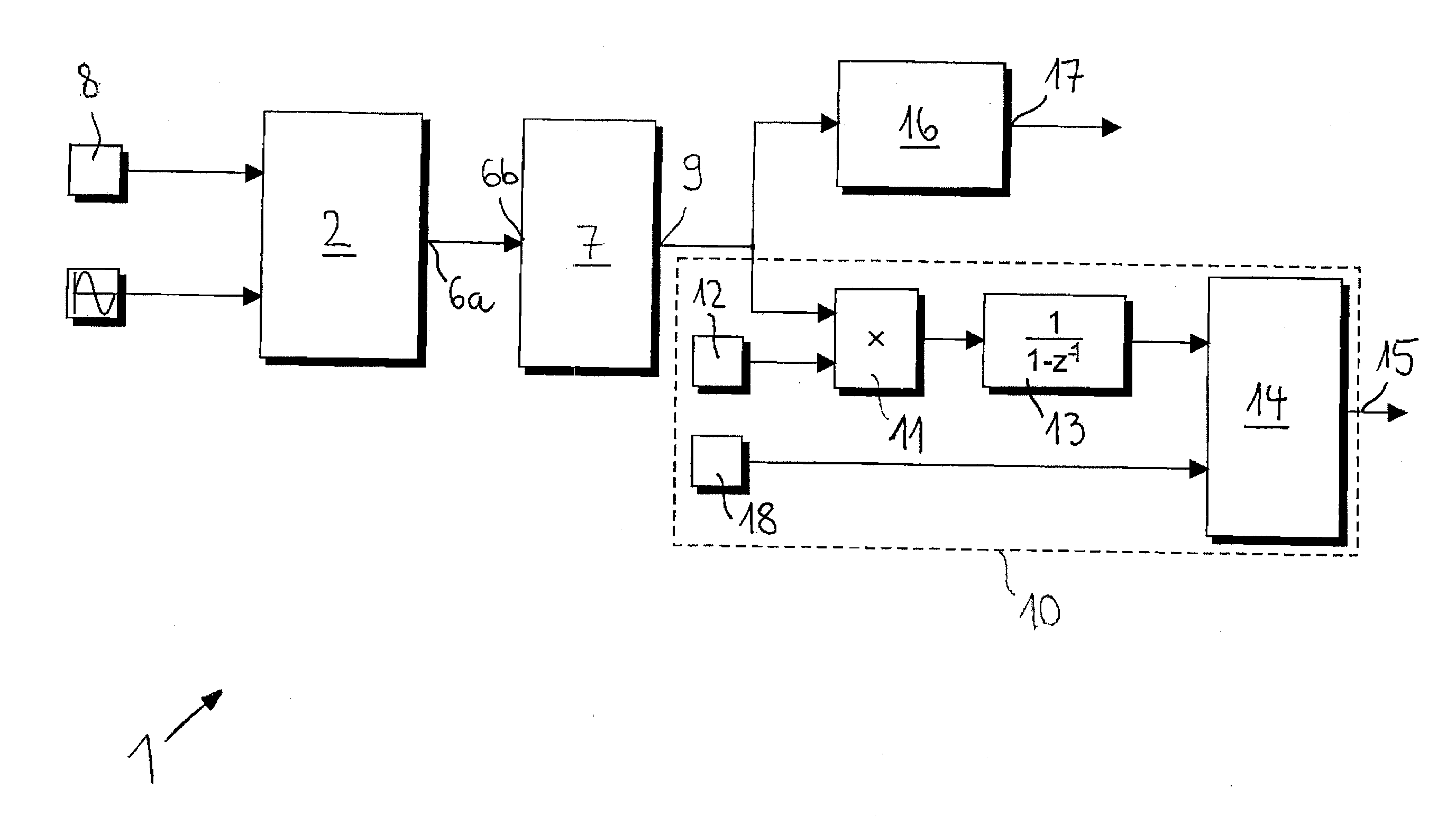
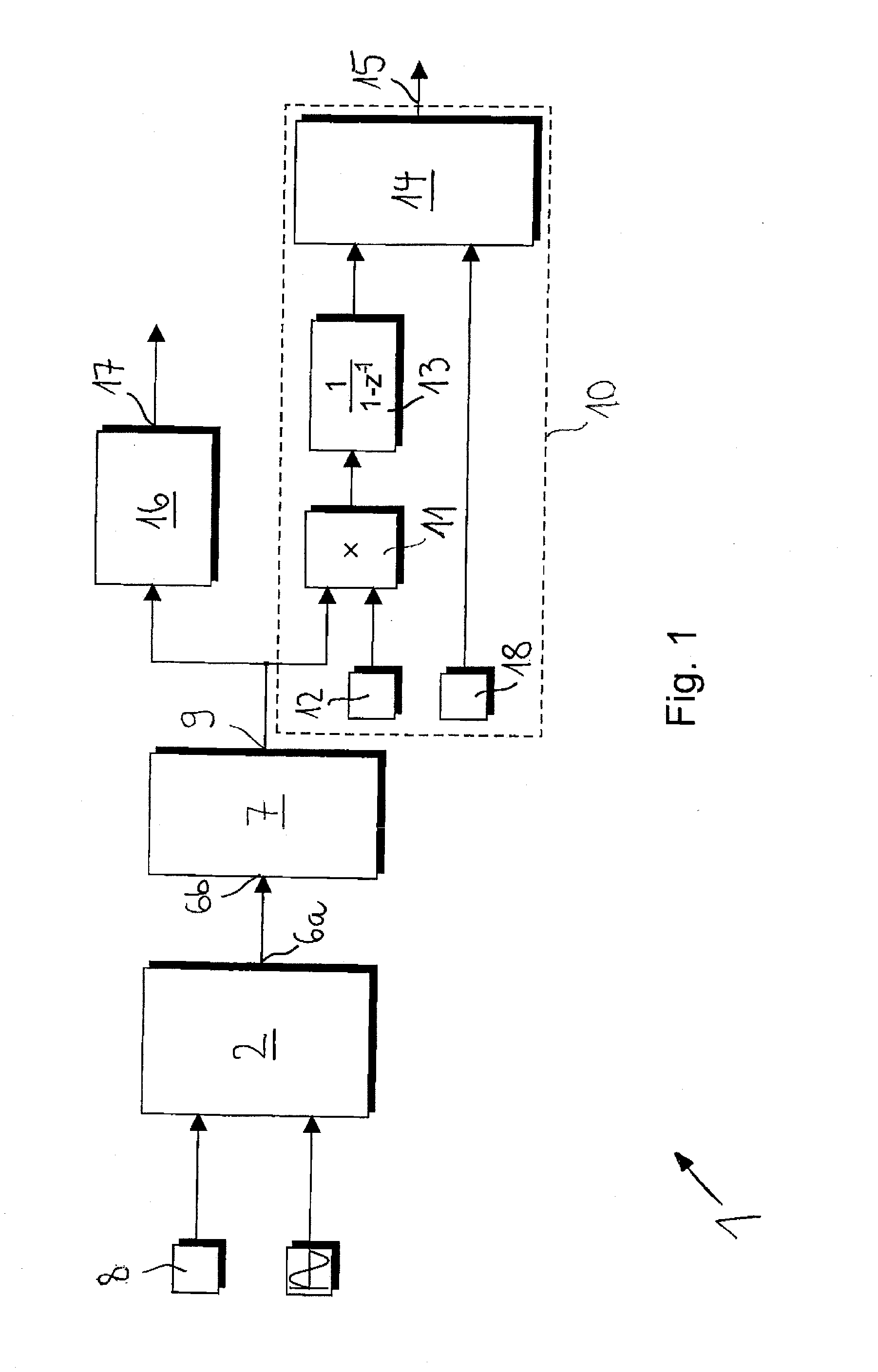
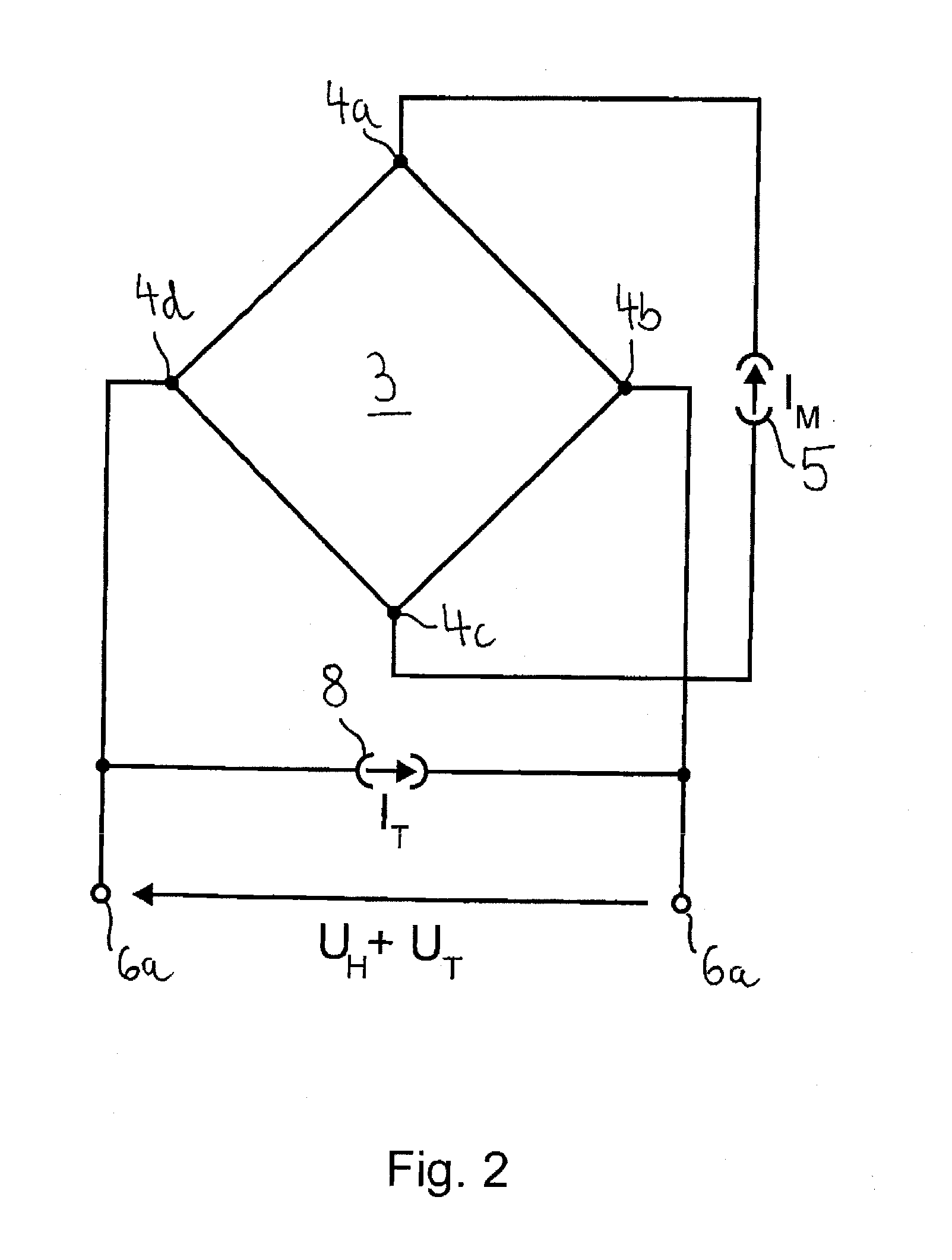
[0033]A sensor module designated as a whole with 1 in FIG. 1 has a semiconductor chip, in whose substrate a sensor 2 is integrated monolithically to measure a magnetic flux density. As is evident in FIG. 2, sensor 2 has a Hall plate 3, which has a first terminal contact 4a, a second terminal contact 4b, a third terminal contact 4c, and a fourth terminal contact 4d.

[0034]The first and third terminal contacts 4a, 4c are spaced apart in a first direction running within the plane of Hall plate 3, and the second and fourth terminal contacts 4b, 4d in a second direction running perpendicular to the first direction within the plane of Hall plate 3. Terminal contacts 4a, 4b, 4c, 4d are connected in a manner known per se to a control unit which is integrated into the substrate and of which only a measuring current source 5 is shown in FIG. 2 for reasons of clarity. A constant electrical current IM is supplied to Hall plate 3 with the use of measuring current source 5. To this end, a first t...


PUM


Abstract

In a method for monitoring the function of a sensor module, which has a sensor, by means of the sensor a measurement signal for a physical quantity to be determined is generated and applied to an output terminal in an unchanged form or in processed form—after at least one linear signal processing step and/or at least one nonlinear signal processing step are performed. In addition, a test signal is generated whose spectrum lies substantially outside the spectrum of the measurement signal. The test signal is supplied at a place in the sensor from which it reaches the output terminal in unchanged form or in processed form—after the performance of the at least one linear signal processing step—only in the case of a functional sensor. An output signal present at the output terminal is compared with the test signal and a diagnosis signal is generated, which indicates whether the test signal is present at the output terminal. The test signal is filtered out of the output signal and the remaining signal is applied as the measurement signal at a measurement signal output of the sensor module.

Description

[0001]This nonprovisional application claims priority under 35 U.S.C. §119(a) to European Patent Application No. EP 10003045.1, which was filed on Mar. 23, 2010, and which is herein incorporated by reference.BACKGROUND OF THE INVENTION[0002]1. Field of the Invention[0003]The invention relates to a sensor module, which has a sensor with a sensor output for outputting a measurement signal for a physical quantity, whereby the sensor output is connected to an output terminal directly or via at least one signal processing stage provided for processing the measurement signal. In addition, the invention relates to a method for monitoring the function of a sensor module, which has a sensor by means of which a measurement signal for a physical quantity to be determined is generated and applied to an output terminal in an unchanged form or in processed form—after at least one linear signal processing step and / or at least one nonlinear signal processing step are performed.[0004]2. Description ...

Claims


Application Information

Patent Timeline
Patent Type & Authority Applications(United States)
IPC IPC(8): H04N17/00
CPCG01D3/08
Inventor BAECHER, DIETERMUTHERS, DAVIDFRANKE, JOERG
Owner TDK MICRONAS GMBH
Why Eureka
Try Eureka