Air conditioning system

a technology of air conditioning system and compressor, which is applied in the direction of refrigeration components, mechanical equipment, light and heating equipment, etc., to achieve the effect of reducing the pressure of excess refrigerant on the suction side of the compressor

Active Publication Date: 2018-06-28
DAIKIN IND LTD
View PDF4 Cites 12 Cited by
  • Summary
  • Abstract
  • Description
  • Claims
  • Application Information

AI Technical Summary

Benefits of technology

[0034]In the air conditioning system having the indoor units provided with the liquid side shut-off valves and the gas side shut-off valves corresponding to the respective indoor units, when closing operation of a liquid side shut-off valve and a gas side shut-off valve has been performed and the compressor operates in the cooling cycle state, in the case in which the liquid side shut-off valve and the gas side shut-off valve operate in the same manner as their closing operation, the flow of the refrigerant into an indoor unit does not occur, and thus, the pressure of the refrigerant on the suction side of the compressor easily drops.
[0035]For this reason, here, as described above, one or some of indoor units are targeted, an

Problems solved by technology

However, the above conventional technique for checking the operation of the shut-off valves using operating noises and/or vibrations cannot determine whether the closed shut-off val

Method used


Image

  • Air conditioning system
  • Air conditioning system
  • Air conditioning system

Examples


first embodiment

(1) Configuration

—Overall Configuration—

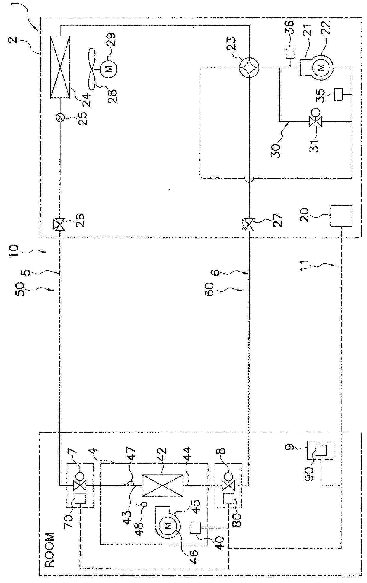
[0055]FIG. 1 is a schematic configuration diagram of an air conditioning system 1 according to a first embodiment of the present invention.

[0056]The air conditioning system 1 is a system performing a vapor compression refrigeration cycle to cool and / or heat a room in a building and the like. The air conditioning system 1 primarily includes a vapor compression refrigerant circuit 10 configured by connecting an outdoor unit 2 to an indoor unit 4 via a liquid refrigerant communication pipe 5 and a gas refrigerant communication pipe 6. The outdoor unit 2 is installed outdoors and primarily has a compressor 21 and an outdoor heat exchanger 24. The indoor unit 4 is installed in a room and has an indoor heat exchanger 42. The refrigerant circuit 10 is filled with refrigerant which is refrigerant having mild flammability such as R32 or refrigerant having high flammability such as R290.

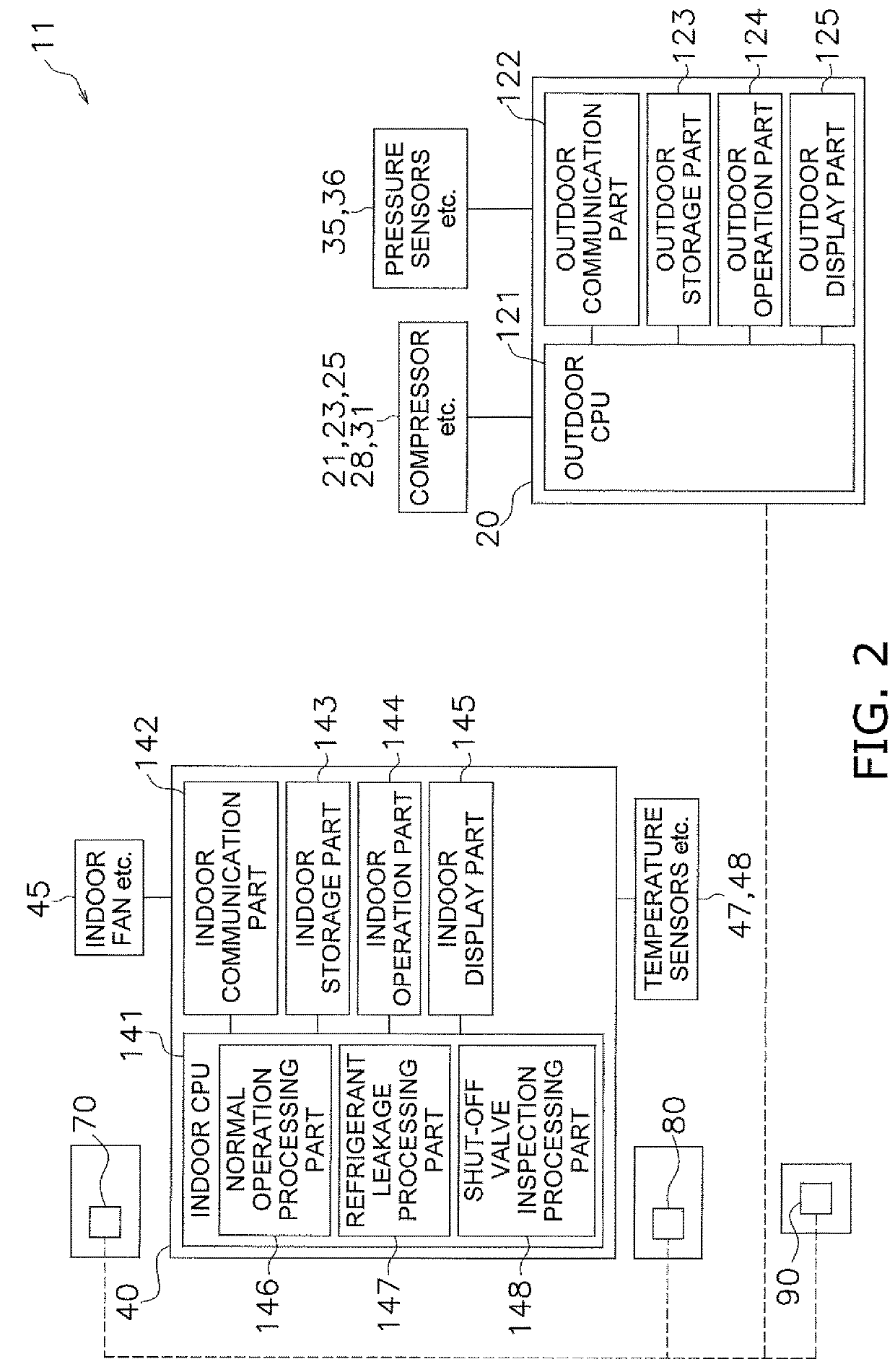
[0057]Moreover, the air conditioning system 1 is also provided with...

second embodiment

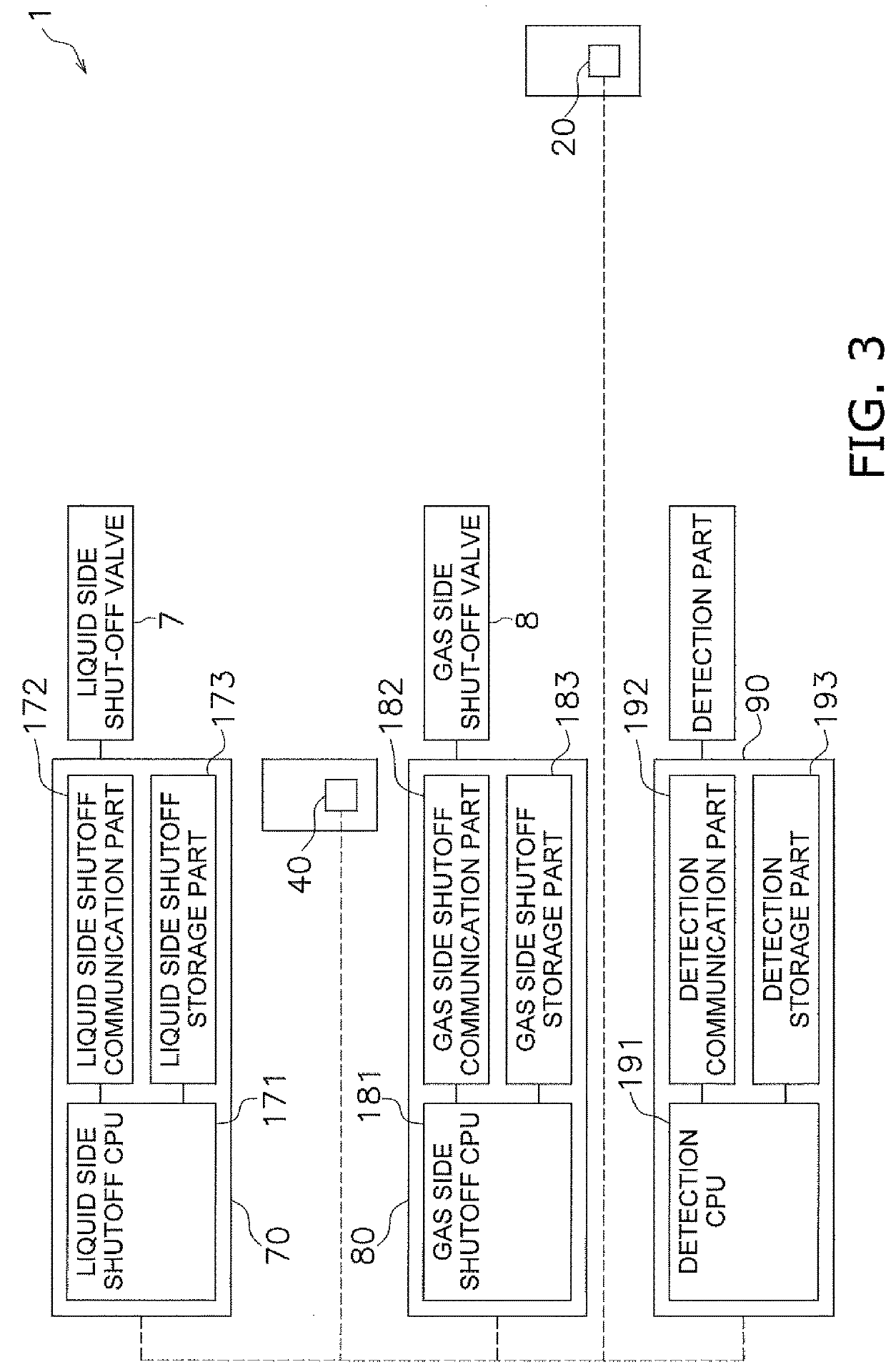
[0120]In the above first embodiment and its modifications, employed is the configuration in which one indoor unit 4 is connected to the outdoor unit 2 via the refrigerant communication pipes 5, 6, the liquid side shut-off valve 7 corresponds to this indoor unit 4 and is provided on the liquid refrigerant pipe 50, and the gas side shut-off valve 8 corresponds to this indoor unit 4 and is provided on the gas refrigerant pipe 60 (see FIGS. 1-3, 5, and 7).

[0121]However, may be employed a configuration in which a plurality of indoor units is connected to the outdoor unit 2 via the refrigerant communication pipes 5, 6, liquid side shut-off valves correspond to the respective indoor units and are provided on the liquid refrigerant pipe 50, and gas side shut-off valves correspond to the respective indoor units and are provided on the gas refrigerant pipe 60.

[0122]As such a configuration, for example, as shown in FIGS. 8 to 10, there is a configuration in which a plurality of (here, two) ind...

modification 1

(3) Modification 1

[0136]Also in the above embodiment, similarly to the modification 1 of the first embodiment, the second predetermined temperature Trl2 used for the determination of whether the liquid side shut-off valves 7a, 7b properly operate may be obtained on the basis of the pressure Ps of the refrigerant detected by the suction pressure sensor 35 at the determination of whether the liquid side shut-off valves 7a, 7b properly operate (at the determination at step ST6).


PUM


Abstract

As a shut-off valve inspection process for checking operation of a liquid side shut-off valve and a gas side shut-off valve, an air conditioning system operates a compressor in a cooling cycle state, performs opening and closing operation of the liquid side shut-off valve and the gas side shut-off valve, and determines whether the liquid side shut-off valve and the gas side shut-off valve properly operate on the basis of a temperature value detected by a temperature sensor provided in an indoor unit.

Description

TECHNICAL FIELD[0001]The present invention relates to an air conditioning system which includes a refrigerant circuit configured by connecting an outdoor unit having a compressor and an outdoor heat exchanger to an indoor unit having an indoor heat exchanger via refrigerant communication pipes and which is provided with a shut-off valve closed when leakage of refrigerant is detected being provided on a liquid refrigerant pipe extending from a liquid side end of the outdoor unit to a liquid side end of the indoor heat exchanger and a shut-off valve closed when leakage of refrigerant is detected being provided on a gas refrigerant pipe extending from a gas side end of the outdoor unit to a gas side end of the indoor heat exchanger.BACKGROUND ART[0002]Conventional air conditioning systems include a refrigerant circuit configured by connecting an outdoor unit having a compressor and an outdoor heat exchanger to an indoor unit having an indoor heat exchanger via refrigerant communication...

Claims


Application Information

Patent Timeline
IPC IPC(8): F25B49/02F24F11/89F25B41/04
CPCF25B49/02F24F11/89F25B41/04F25B2600/2501F25B2600/2519F25B13/00F25B2313/006F25B2313/0314F25B2500/221F25B2500/222F25B2600/23F25B2700/2104F25B41/20F25B41/24
Inventor HONDA, MASAHIROKAMITANI, SHIGEKI
Owner DAIKIN IND LTD
Why Eureka
Try Eureka