Wireless Passive Radio-Frequency Strain And Displacement Sensors

a passive radiofrequency and sensor technology, applied in the direction of fluid pressure measurement, fluid pressure measurement by electric/magnetic elements, instruments, etc., can solve the problems of fragility and susceptibility to damage, low cost and easy installation of resistive metal foil strain gauge sensors, and physical connection between the sensor and the interrogation unit is also prone to corrosion and fracture, and achieves the effect of prolonging the fatigue li

Active Publication Date: 2012-11-29
UNIV OF MASSACHUSETTS
View PDF12 Cites 24 Cited by
  • Summary
  • Abstract
  • Description
  • Claims
  • Application Information

AI Technical Summary

Benefits of technology

The invention provides strain sensors that have longer fatigue lives than conventional sensors. This is because the rigid substrates used in the invention prevent deformation of the sensing elements during application of a tensile or compressive load. Instead, the interlayer, which is typically made of an elastomer or other insulating material, can undergo millions of deformation cycles before failure. This makes the sensors more suitable for measuring stress and strain in bridges, buildings, aircraft, and other structures than conventional strain sensors.

Problems solved by technology

The technical problem addressed in this patent is the need for a strain sensor that is light-weight, cost-effective, and easy to install, and can measure considerable strains over large areas of structures without succumbing to corrosion, damage, or performance degradation over time. Current strain sensors, such as resistive metal foil strain gauges and fiber-optic based sensors, have limitations and may fail too soon for long-term sensing applications. There is also a need for a strain sensor that can wirelessly monitor strains in the absence of a clear line of sight or physical connection to the structure of interest.

Method used


Image

  • Wireless Passive Radio-Frequency Strain And Displacement Sensors
  • Wireless Passive Radio-Frequency Strain And Displacement Sensors
  • Wireless Passive Radio-Frequency Strain And Displacement Sensors

Examples


example 1

Tensile and Compressive Load Measurement

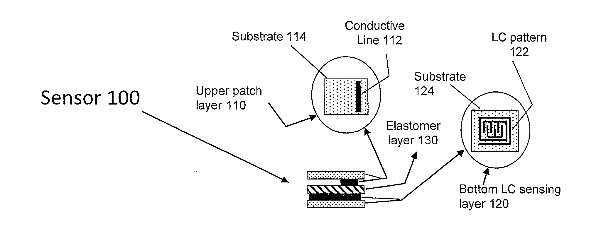
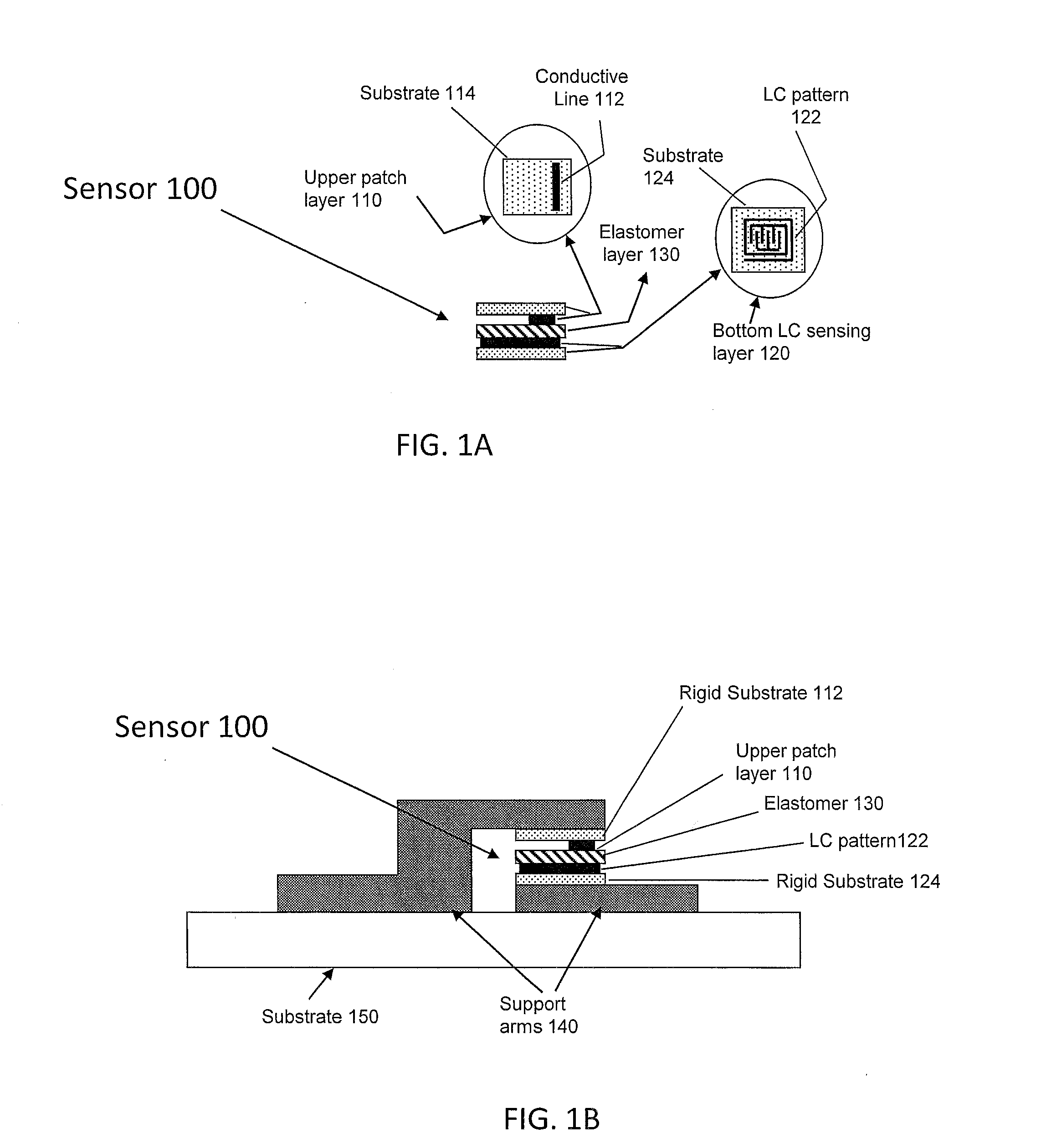
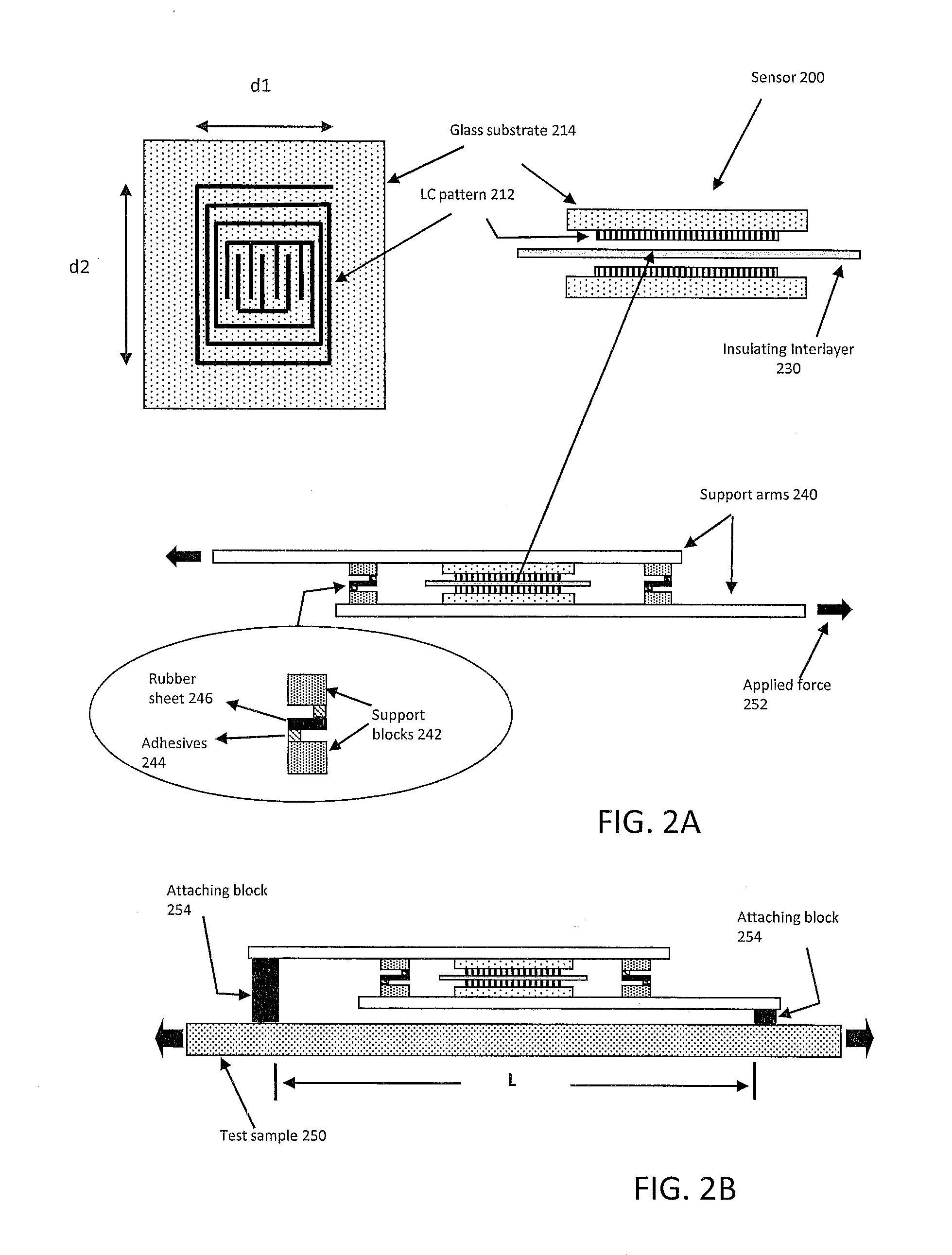
[0040]Interdigital capacitance and meander inductance patterns were prepared by screen printing technology as described above to form upper and lower sensing layers. The size of LC pattern (lower layer) is 40 mm×40 mm, and line pattern of upper patch layer 30 mm×3 mm. An adhesive elastomer layer was inserted between the two conductive layers as shown in FIGS. 1A and 2A to create the sensor. The RF response of strain sensors was measured using a vector network analyzer in reflection mode (i.e., an S11 measurement). The vector network analyzer transmitted a swept RF signal to the strain sensor, which absorbed the incident RF signal at a resonance whose center frequency varied with the applied load.

[0041]FIG. 5 shows a plot of resonant frequency shift caused by a tensile load applied to a strain sensor similar to sensor 100 of FIG. 1. Alternating solid, dashed, and dotted lines show that the absorption resonance (a valley with an amplitude of abo...

example 2

Cracked Sensor Interrogation

[0045]Detection of cracks and structural damage in the absence of clear line of sight detection is still an important challenge. Fortunately, the RF-based measurements described herein can be applied to the detection of cracks in various structures, including ceramic plates used in body armor. Structural damage, such as a crack on a ceramic plate, leads to a detectable change in the RF response. The ultimate sensitivity of the measured RF response is determined by the size of the metal flake present in the silver ink used for the fabrication of the sensor. The success of these sensors ultimately depends on their performance and ease of manufacture.

[0046]Most RF-based inductor-capacitor (LC) resonant sensors reported to date are fabricated using techniques such as photolithography, inkjet printing, thermal spray, and laser micromachining. In this example, a sensor was created using the screen-printing techniques described above. Conductive silver inks were...

example 3

Passive Wireless Sensor Arrays

[0050]Sensors and sensing elements may also be arranged in periodic or aperiodic arrays. In addition, different sensors and sensing elements in the array(s) may be oriented in different directions, depending on the application. Because the individual sensors are displaced from each other and / or oriented in different directions, each sensor measures a projection of the applied displacement along a different basis (set of axes). These measurements can be used to trace the direction of displacement or applied strain by measuring the change in resonant frequency profile of each of the sensors caused by the relative displacement of the sensing element on complementary layers.

[0051]FIG. 10 shows an example sensor 900 with four sensing elements 902a-902d (LC1, LC2, LC3, and LC4) printed on a single surface to formed a single sensing layer. Another sensing element 904 (LC0) was printed on an upper surface to form a complementary sensing layer. The upper sensing...


PUM

PropertyMeasurementUnit
Electrical conductivityaaaaaaaaaa
Adhesivityaaaaaaaaaa
Frequencyaaaaaaaaaa

Abstract

Wireless strain and displacement sensors wirelessly monitor structural health and integrity, and are made by printing inductor-interdigital capacitor sensing circuits on a variety of substrates, including ceramic substrates, with thermally processable conductive inks. Sensors of the invention can be employed to detect strain and displacement of civil structures, such as bridges and buildings. The sensors include sensing elements that are mounted or printed on stiff, inflexible substrates, which prevent the sensing elements from bending, stretching, or otherwise warping when the sensor is strained. An interlayer between the sensing elements allows the sensing elements to move with respect to each other during application of strain. Thus, strain causes the sensing elements to move but not to deform, causing changes in sensor resonance that can be detected through wireless radio-frequency interrogation. Because the sensing elements do not change shape when under strain, the sensor can undergo millions of measurement cycles before breaking.

Description


Claims


Application Information

Patent Timeline
Owner UNIV OF MASSACHUSETTS
Why Eureka
Try Eureka