
Terrain visualization device

a technology for visualization devices and terrain, applied in the field of terrain visualization devices, can solve the problems of poor lighting conditions, difficult for skiers to see the topography of the terrain without sunlight, and may not produce shadows in the snow

Inactive Publication Date: 2012-11-29
STEVENS JULIAN
View PDF18 Cites 13 Cited by
  • Summary
  • Abstract
  • Description
  • Claims
  • Application Information

AI Technical Summary

Benefits of technology

"The patent describes a device that allows users to see the topography of terrain even in poor lighting conditions. The device uses a light emitting unit that projects a predetermined contrast pattern onto the terrain. This pattern is distorted by the terrain, and the user can easily infer the shape of the terrain by analyzing the distortion. The device is designed to use less energy than traditional illumination devices, as it only requires a small amount of power to create the contrast pattern. The light emitting unit can be a laser light source or a superluminescent diode light source. The predetermined contrast pattern can be a line, a dot, or a combination of lines and dots. The device can be attached to a belt, head strap, helmet, ski, mono-ski, snowboard, shoe, or boot. The method for using the device involves fixing the mounting structure to the user and then traversing the terrain while projecting the predetermined contrast pattern onto the terrain."

Problems solved by technology

There is a common problem encountered in skiing when lighting conditions are poor, whether due to low cloud or the time of day.
In such conditions, sunlight may not produce shadows on the snow, either due to the sun being obscured by cloud or due to the position of the sun in the sky.
It is very difficult for a skier to see the topography of the terrain without shadows on the snow because the snow-covered ground appears as a uniform white sheet, without colour color or luminance contrast.
The above problem is particularly dangerous in winter sports such as skiing, snowboarding and mono-skiing, where it can lead to accidents caused by the skier unexpectedly either leaving the ground or hitting a bump in the snow.
However, the same problem is encountered when traversing snow-covered ground by any means including walking and driving a vehicle.
A similar problem is also encountered when traversing other types of terrain that are uniform in appearance and do not provide sufficient color or luminance contrast to see their topography in poor light.
For example, the problem can also be encountered in water sports such as waterskiing in low light, or when hiking at night.

Method used


Image

  • Terrain visualization device
  • Terrain visualization device
  • Terrain visualization device

Examples


Embodiment Construction

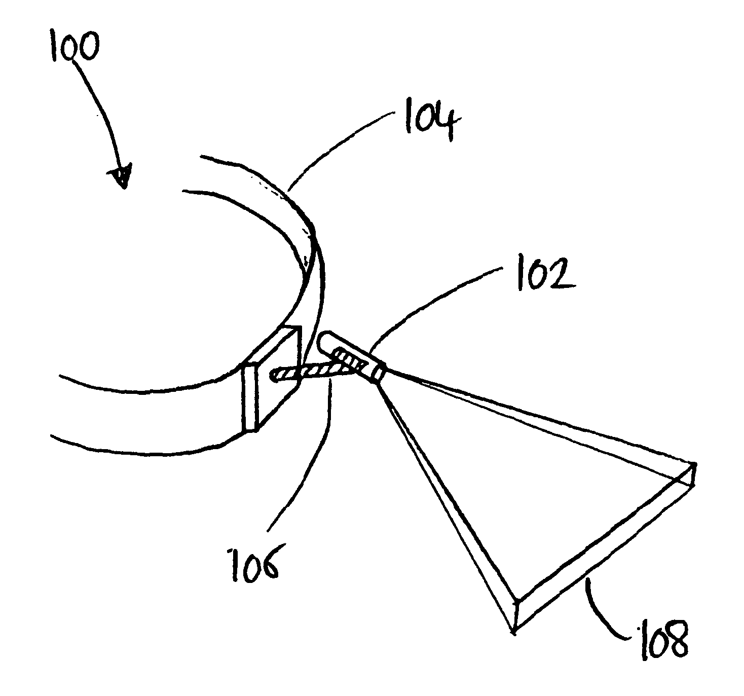
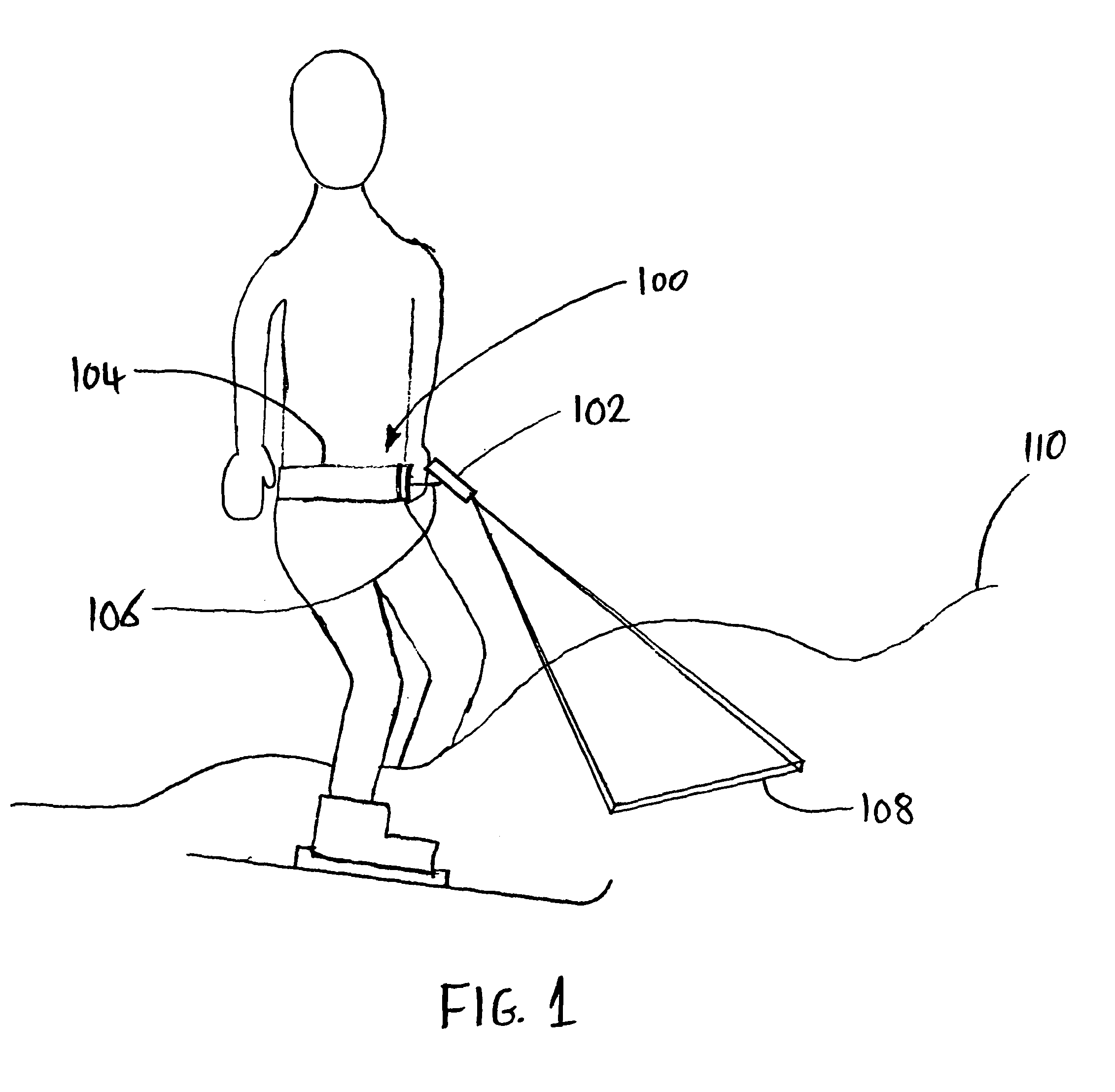
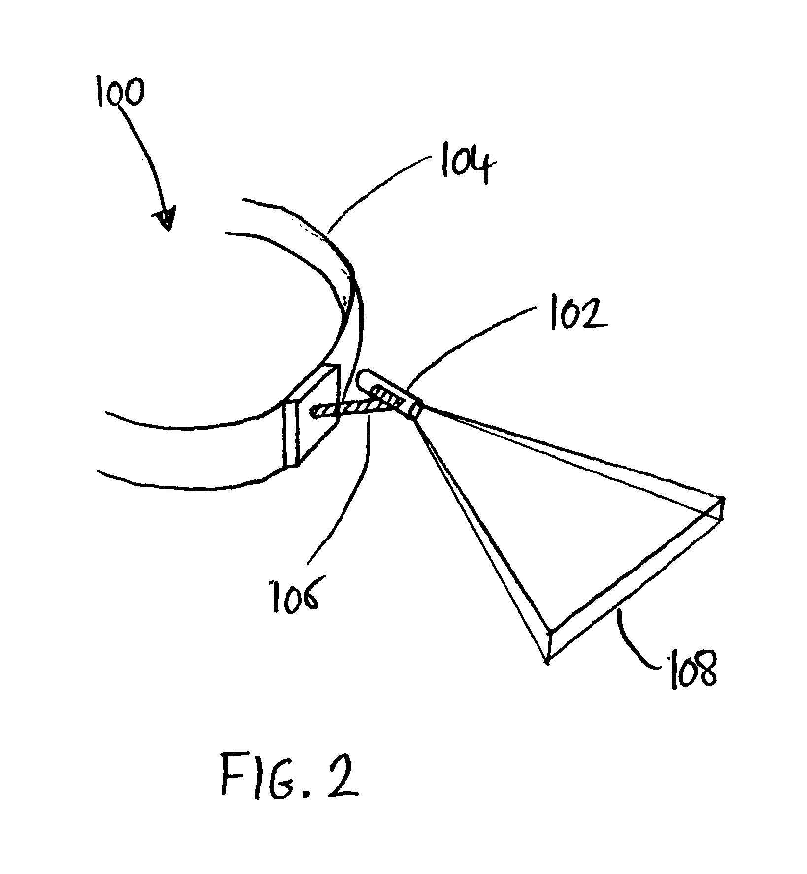
[0037]As shown in FIGS. 1 and 2, a device 100 according to an embodiment includes a light emitting unit 102 attached to a mounting structure 104. The mounting structure 104 includes a belt and a light source holder 106. The device 100 projects a predetermined contrast pattern of light 108 onto terrain 110 in front of a user.

[0038]In this embodiment, the light emitting unit 102 comprises a laser diode and complies with the ANSI Z136 and IEC 60825 standards. However, any light source sufficiently bright and directional to project a contrast pattern onto a terrain surface from a distance of a few meters can be used. In particular, a coherent light source is not required and a non-coherent source such as a superluminescent diode (SLED) can be used instead.

[0039]The power of the light source must be sufficient in embodiments for the user to see the contrast pattern projected by the light source onto the ground. However, the light source must not be so powerful that it could cause eye inj...


PUM


Abstract

A terrain visualization device is disclosed, the device comprising a wearable mounting structure adapted to be fixed to a user. The device also includes a light emitting unit attached to the mounting structure and configured to project a predetermined contrast pattern onto terrain when the mounting structure is fixed to a user. Also disclosed is a method for traversing terrain comprising fixing a wearable mounting structure to a user, the mounting structure having a light emitting unit attached thereto, traversing the terrain, and projecting a predetermined contrast pattern onto the terrain using the light emitting unit, so that the topography of the terrain can be determined from distortion of the contrast pattern. A method for illuminating a ski run is also disclosed.

Description

RELATED APPLICATIONS[0001]The present application is a National Phase entry of PCT Application No. PCT / GB2011 / 000955, filed Jun. 24, 2011, which claims priority from Great Britain Application Number 1014599.3, filed Sep. 2, 2010, the disclosures of which are hereby incorporated by reference herein in their entireties.FIELD OF THE INVENTION[0002]The present invention relates to a terrain visualization device that projects a pattern of light onto the terrain, allowing a user to see the topography of the terrain even in poor lighting conditions. The invention also relates to a method for traversing terrain and a method for illuminating a ski run.BACKGROUND[0003]There is a common problem encountered in skiing when lighting conditions are poor, whether due to low cloud or the time of day. In such conditions, sunlight may not produce shadows on the snow, either due to the sun being obscured by cloud or due to the position of the sun in the sky. It is very difficult for a skier to see the ...

Claims


Application Information

Patent Timeline
Patent Type & Authority Applications(United States)
IPC IPC(8): F21V21/08G21K5/00F21V21/084
CPCG01B11/2513
Inventor STEVENS, JULIAN
Owner STEVENS JULIAN
Learn More