
Replaceable sawing surface device and method

a sawing surface and support device technology, applied in metal sawing equipment, metal-working equipment, manufacturing tools, etc., can solve the problems of saw blade striking a support, affecting the cutting process, and burdening cutting material provisions,

Active Publication Date: 2012-11-29
BLICK JOHN
View PDF4 Cites 5 Cited by
  • Summary
  • Abstract
  • Description
  • Claims
  • Application Information

AI Technical Summary

Benefits of technology

[0008]The invention is a combination which includes a sacrificial board and its stabilizing support which form an assembly which may be referred to as a saw cup. The support has a bottom structure which includes a vacuumable surface and a lower skirt which enables it to become registered and used in conjunction with a vacuum support. The saw cup assembly is a much quicker approach to achieving the desired results of providing a surface which is scorable by a small degree and is easily repairable and replaceable. Damage to any one small piece can be much more easily and inexpensively repaired or replaced. The suctions cups are normally provided and place for other, non-sawing operations. The cement board at the top of the saw cup can be scorably cut multiple times before replacement is required. In short, the saw cup prevents cutting into the top of the vacuum hold down support which is normally used for other operation with intentional sacrificial scoring of the saw cup. This enables double use of the vacuum hold down support which is normally used for non-sawing operations.
[0010]The saw cup of the invention enables CNC machine users to go back and forth between the two operations of cutting and of edge shaping with minimum time. To switch from sawing to edge and finishing operations, the saw cups are simply picked up off of the vacuum hold down supports and temporarily stored. Likewise, to switch from edge and finishing operations to sawing of the next piece of material, the saw cups are quickly and simply replaced upon the vacuum hold down supports without having to re-arrange the vacuum hold down supports. The location of the vacuum hold down supports can be pre-set and geared to a configuration associated with the shapes that will be set up for edge finishing.
[0012]The result is the ability to use a vacuum hold down and containment lid assembly as a support for a slab of material to be cut. Further, the cement board supported by the containment lid can be scarred many dozens or hundreds times before needing to be replaced. When a heavy slab is being processed, the weight of the slab onto the cement board supported by the containment lid is enough to prevent lateral shifting of the slab. Further, because the support areas for the material to be cut are distributed and isolated, in many cases the saw will cut material lying over a raised space over the table. A second embodiment of a containment lid provides a disposable support which can laterally register a sacrificial board and is of such inexpensive construction that it can be discarded once it has undergone a high number of sacrificial cuts in the cutting operation.

Problems solved by technology

Both of these typical provisions for cutting material are burdensome.
One miscalculation can cause the saw blade to strike a support and damage it or the saw blade.
In the case of a re-dressable table, operations must stop once the table is scarred to the extent that it is no longer able to evenly support the material to be cut.
In addition a dressed table committed to a sawing operation is limited in its other uses.
In the case of vacuum supports, operators who wish to perform sawing operations have been limited to using the known free path method.
Further, the placement of the vacuum hold downs to avoid sawing of the vacuum supports will normally not be in the same layout placement of the vacuum supports needed in properly supporting the slabs of material to be edge shaped.
Even one vacuum hold down which is improperly placed, or even one cutting error can cause severe and costly damage.
This type of sacrificial board assembly is heavy and requires two or more workers to handle it effectively.
This large piece can be very expensive, difficult to handle, and is easily damaged.
Once damaged this large piece of material must be replaced at a significant cost.

Method used


Image

  • Replaceable sawing surface device and method
  • Replaceable sawing surface device and method
  • Replaceable sawing surface device and method

Examples


Embodiment Construction

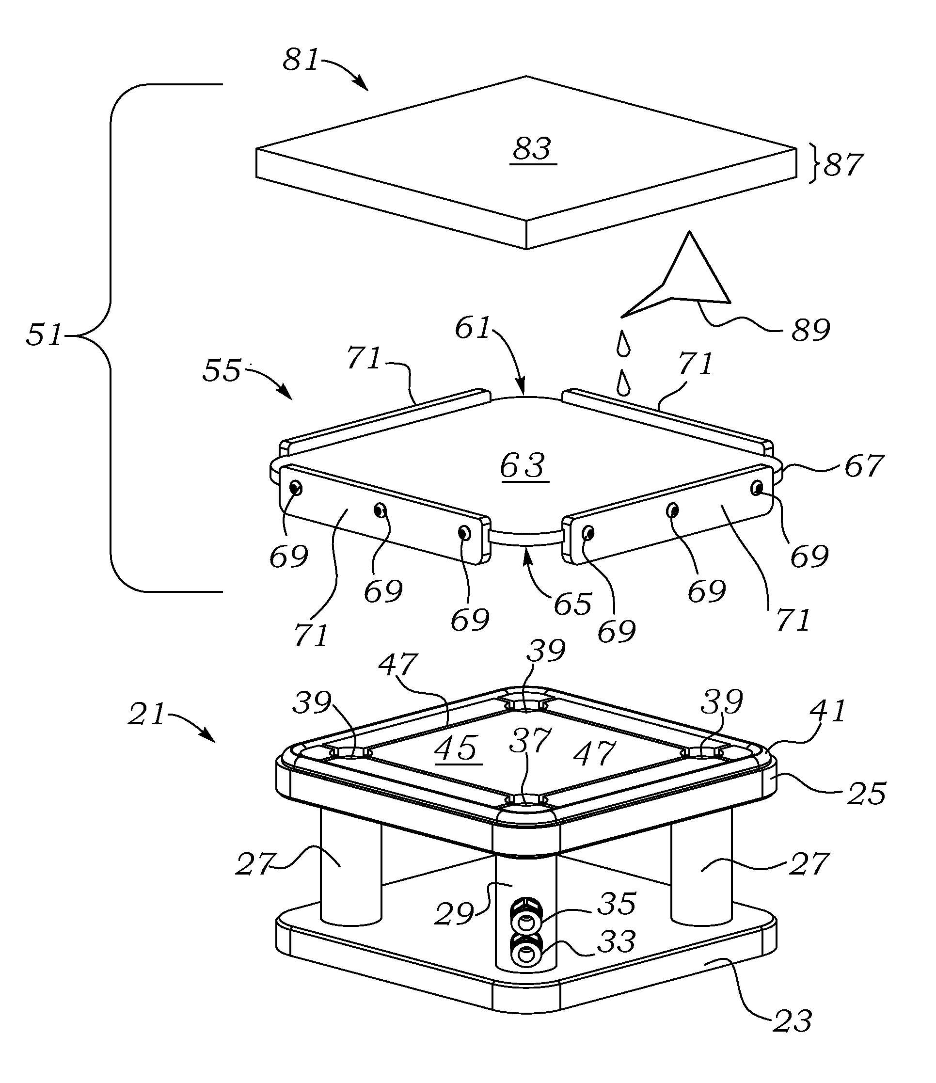
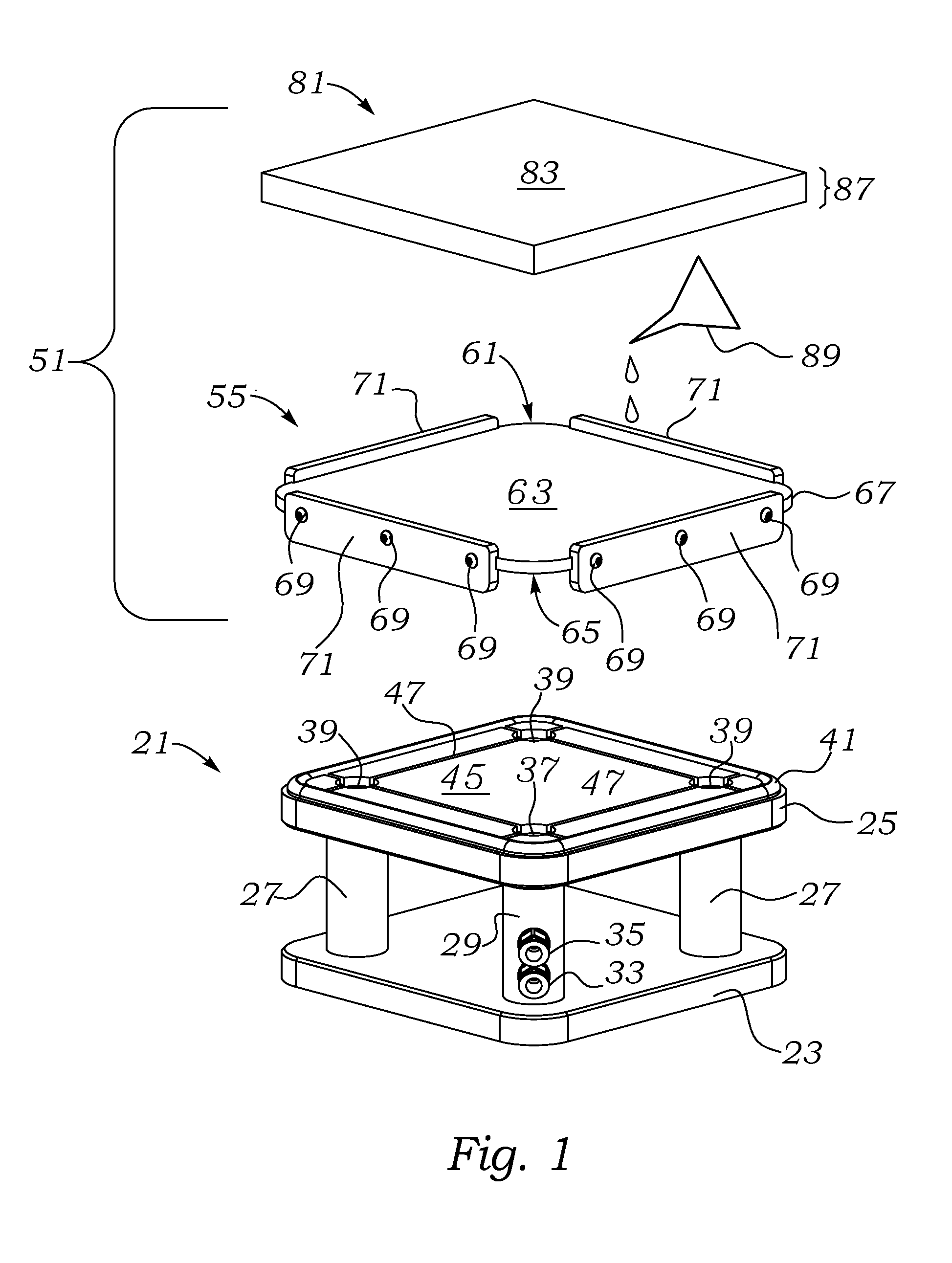
[0021]Referring to FIG. 1, a perspective of a vertical exploded view of the containment lid assembly of the invention overlying a vacuum hold down is shown. Beginning at the bottom of the Figure, a perspective view of a vacuum hold down support 21 is shown. Vacuum hold down support 21 can be of any height, area or shape including round, rectangular, irregular or square, but the embodiment shown has an overall square shape to maximize the area of support and to illustrate a simple construction.

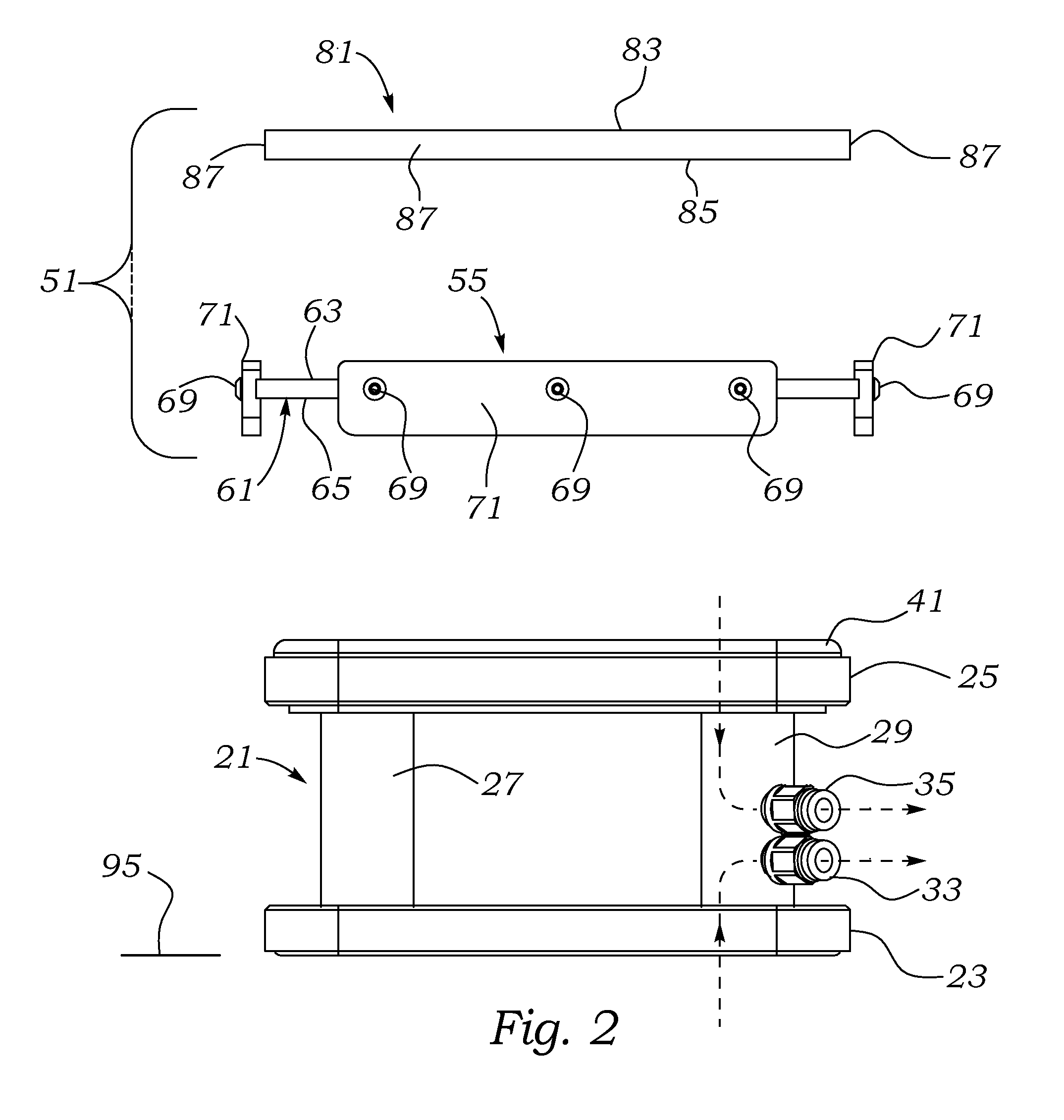
[0022]The vacuum hold down support 21 has a base 23 at its lowermost extent and a top 25. The vacuum hold down support 21 has a set of four support columns 27 of which only three are seen, and one of which is a vacuum transmission column 29. Columns 27 and 29 support the top 25 with respect to the base 23. Vacuum transmission column 29 which supports a first vacuum input port 33 in communication with the area underneath the base 23 (to provide vacuum hold down of the vacuum hold down support 21...


PUM

PropertyMeasurementUnit
Dimensionaaaaaaaaaa
Softnessaaaaaaaaaa

Abstract

A system which includes a sacrificial board such as a cement board and containment support lid, sometimes referred to as a saw cup, is provided for use with a vacuum hold down support to allow cutting on top of normal suction cups by providing a temporary scorable surface in an assembly that is easily installed and removed, inexpensive to own, use and handle and which enables a user to go directly back to using a CNC machine for final edging and processing of the material without having to go to another location for sawing and without having to deal with heavy and unwieldy plates. The dimensions of the cement board and containment lid are such that any penetration of the cutting blade is intentional and will result in controlled scarring of the cement board which does not disable continued use of the saw cup. A one-piece molded saw cup is also illustrated.

Description

FIELD OF THE INVENTION[0001]The present invention relates to improvements in the field of quick setup work holding and support devices for sawing work. More specifically, the present invention relates to a device and method used to support heavy sheet and slab type materials of various thicknesses for dimensional cutting with circular sawing attachments such as the type employed by computer numerically controlled milling machines using typically unevenly spaced conventional vacuum hold down support devices, as well as on bridge saws and other types of saws which might be configurable for non-sawing purposes, both of which may be provided with an expendable replaceable sawing cup which includes a sacrificial material supported by a laterally registered support of a known height.BACKGROUND OF THE INVENTION[0002]Computer numerically controlled milling machines are used to process (such as edge finishing) sheet type materials of various material composition, shape, and dimensions and ar...

Claims


Application Information

Patent Timeline
IPC IPC(8): B25B11/00
CPCB25B11/005B23D47/025
Inventor BLICK, JOHN
Owner BLICK JOHN
Learn More