Transmission shaft having centrifugal device and transmission method thereof

a transmission shaft and centrifugal technology, applied in the direction of motor/generator/converter stopper, dynamo-electric converter control, machine/engine, etc., can solve the problems of energy loss, energy consumption, transmission shaft energy loss during transmission, etc., to reduce energy consumption, energy generated, and energy consumption.

Inactive Publication Date: 2012-11-29
SHEN YANG TECH ENTERPRISE
View PDF10 Cites 2 Cited by
  • Summary
  • Abstract
  • Description
  • Claims
  • Application Information

AI Technical Summary

Benefits of technology

[0006]The present invention provides a transmission shaft having a centrifugal device. When a driven device generates a certain amount of energy, the transmission shaft having the centrifugal device may reduce energy consumed by a driving device to drive the driven device, and may further make energy generated by the driven device greater than the energy consumed by the driving device to drive the driven device, thereby effectively reducing consumption of earth resources and effectively solving a problem of earth environmental protection.

Problems solved by technology

However, such energy resources all have problems, for example, the energy resources may be exhausted, or have technical problem to be solved in usage, or have great danger in use.
When a transmission shaft transmits motive power to a power generation device to generate electric power, or transmits motive power to a power device to generate a driving force, a driving device and a driven device both have energy dissipation, and the transmission shaft also has energy loss during transmission.
As a result, an entire efficiency is reduced, and therefore more energy needs to be consumed, thereby causing more problems of earth environmental protection.

Method used


Image

  • Transmission shaft having centrifugal device and transmission method thereof
  • Transmission shaft having centrifugal device and transmission method thereof
  • Transmission shaft having centrifugal device and transmission method thereof

Examples


Embodiment Construction

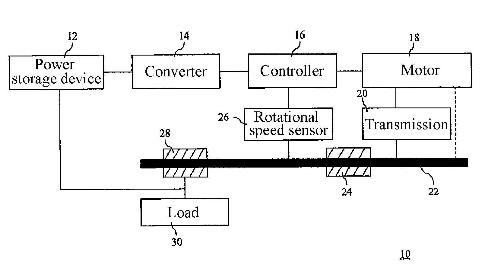
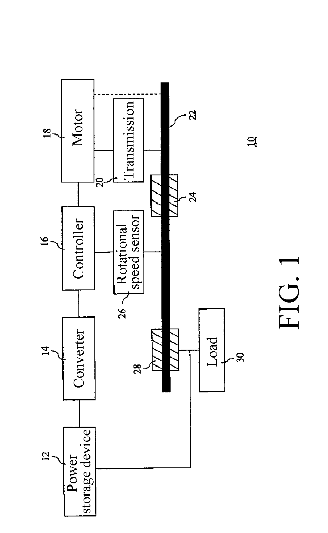
[0034]A transmission shaft of the present invention is disposed between a driving device and at least one driven device, and at least one centrifugal device is disposed on the transmission shaft. The driving device may be a water turbine, a gas turbine, a motor, an engine, a turbine, a steam engine or a blade (applied to a wind driven generator). The at least one driven device may be a generator or a motion mechanism (such as a wheel or a screw-propeller) of a car or a steamship.

[0035]The driving device rotates the transmission shaft and propels the at least one centrifugal device. With rotation of the transmission shaft, the at least one centrifugal device generates a centrifugal force. When the driving device drives the transmission shaft to rotate at a preset rotational speed, the centrifugal force of the at least one centrifugal device forms an inertia effect which is applied to the transmission shaft. The transmission shaft having kinetic energy of the rotation of the driving d...


PUM


Abstract

A transmission shaft is disposed between a driving device and at least one driven device. At least one centrifugal device is disposed on the transmission shaft. The centrifugal device generates a centrifugal force and applies an inertia affect formed by the centrifugal force to the transmission shaft, so as to drive the transmission shaft to rotate. Energy generated by the driven device is greater than energy consumed when the driving device drives the driven device, thereby effectively reducing the consumption of earth resources and effectively solving a problem of earth environmental protection.

Description

BACKGROUND OF THE INVENTION[0001]1. Field of Invention[0002]The present invention relates to a transmission shaft having a centrifugal device and disposed between a driving device and a driven device, and a transmission method thereof.[0003]2. Related Art[0004]As people's quality of life improves gradually, electrical appliances and power equipment (such as cars and steamships) are widely used in life or work. And energy resources of the electrical appliances and the power equipment are mostly petroleum, natural gas, solar energy and nuclear power. However, such energy resources all have problems, for example, the energy resources may be exhausted, or have technical problem to be solved in usage, or have great danger in use.[0005]When a transmission shaft transmits motive power to a power generation device to generate electric power, or transmits motive power to a power device to generate a driving force, a driving device and a driven device both have energy dissipation, and the tra...

Claims


Application Information

Patent Timeline
Patent Type & Authority Applications(United States)
IPC IPC(8): H02K47/00H02P7/06F16F15/30F16H63/00F03G7/10
CPCF03G7/10Y10T477/675Y10T74/2117
Inventor TSAI, HUI YENCHENG, WEN-LONFAN, CHIU-RONGCHUANG, TIEN
Owner SHEN YANG TECH ENTERPRISE
Why Eureka
Try Eureka