Syringe drive device and syringe drive method

a drive device and syringe technology, applied in the field of syringe drive devices, can solve the problems of the work load of the operator handling the syringe, and achieve the effects of improving the accuracy of detection of a very small internal pressure of the syringe, improving the safety of mixing injection drugs, and improving the accuracy of syringe detection

Inactive Publication Date: 2012-11-29
PANASONIC CORP
View PDF6 Cites 16 Cited by
  • Summary
  • Abstract
  • Description
  • Claims
  • Application Information

AI Technical Summary

Benefits of technology

[0016]The syringe drive device and the method of controlling the syringe drive device according to the present invention realize alerting an operator in advance to occurrence of a medicinal solution aerosolization, which achieves a safe operation of mixing injection drugs. In particular, because the movable section is provided so as to be elastically biased to the plunger of the syringe, it is possible to improve accuracy in detection of a very small internal pressure of the syringe, resulting in that an operator can be alerted to occurrence of medicinal solution aerosolization with a higher degree of accuracy.

Problems solved by technology

Accordingly, it is quite a workload for an operator to handle a syringe in order to mix medicinal solutions.

Method used


Image

  • Syringe drive device and syringe drive method
  • Syringe drive device and syringe drive method
  • Syringe drive device and syringe drive method

Examples


first embodiment

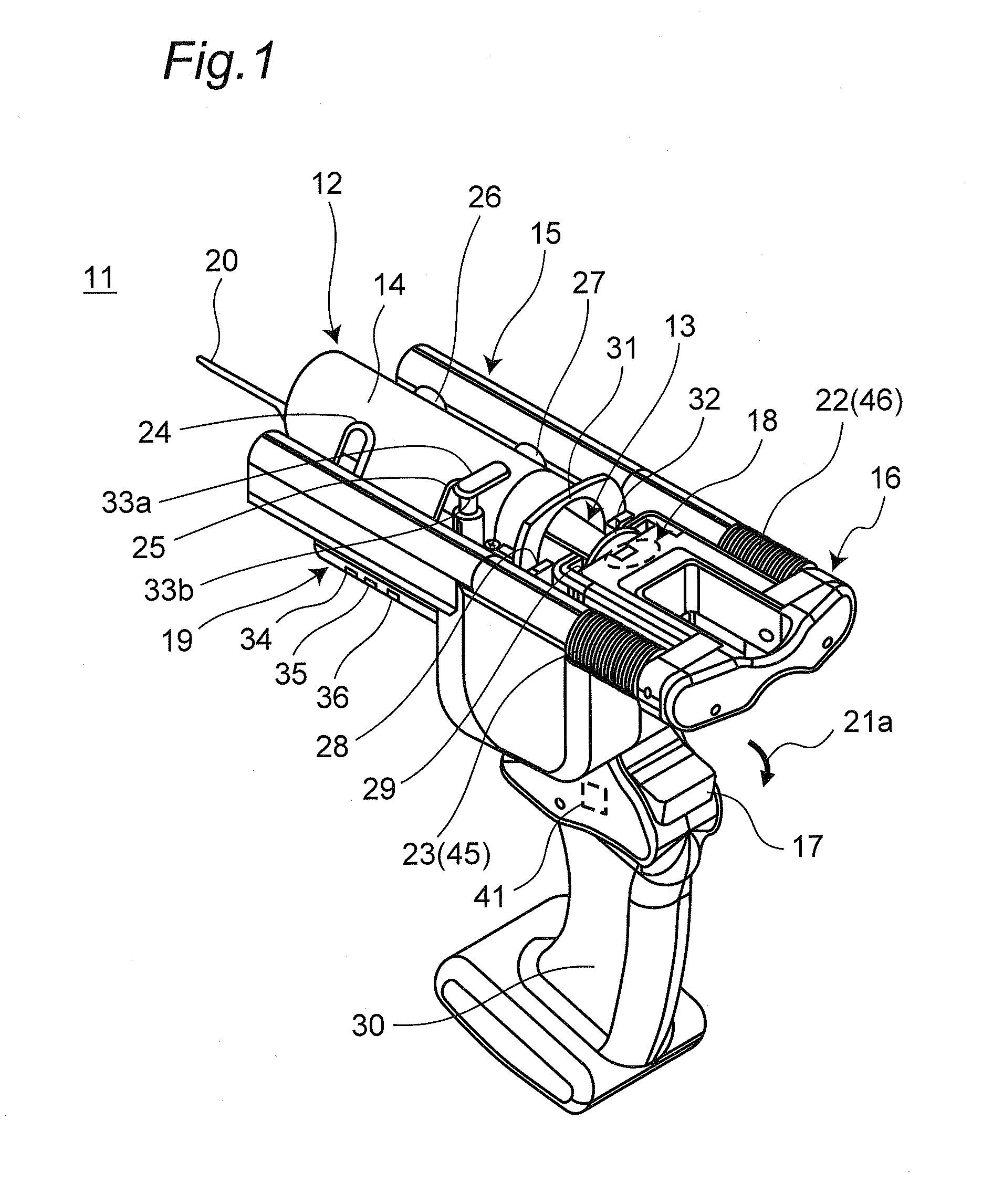
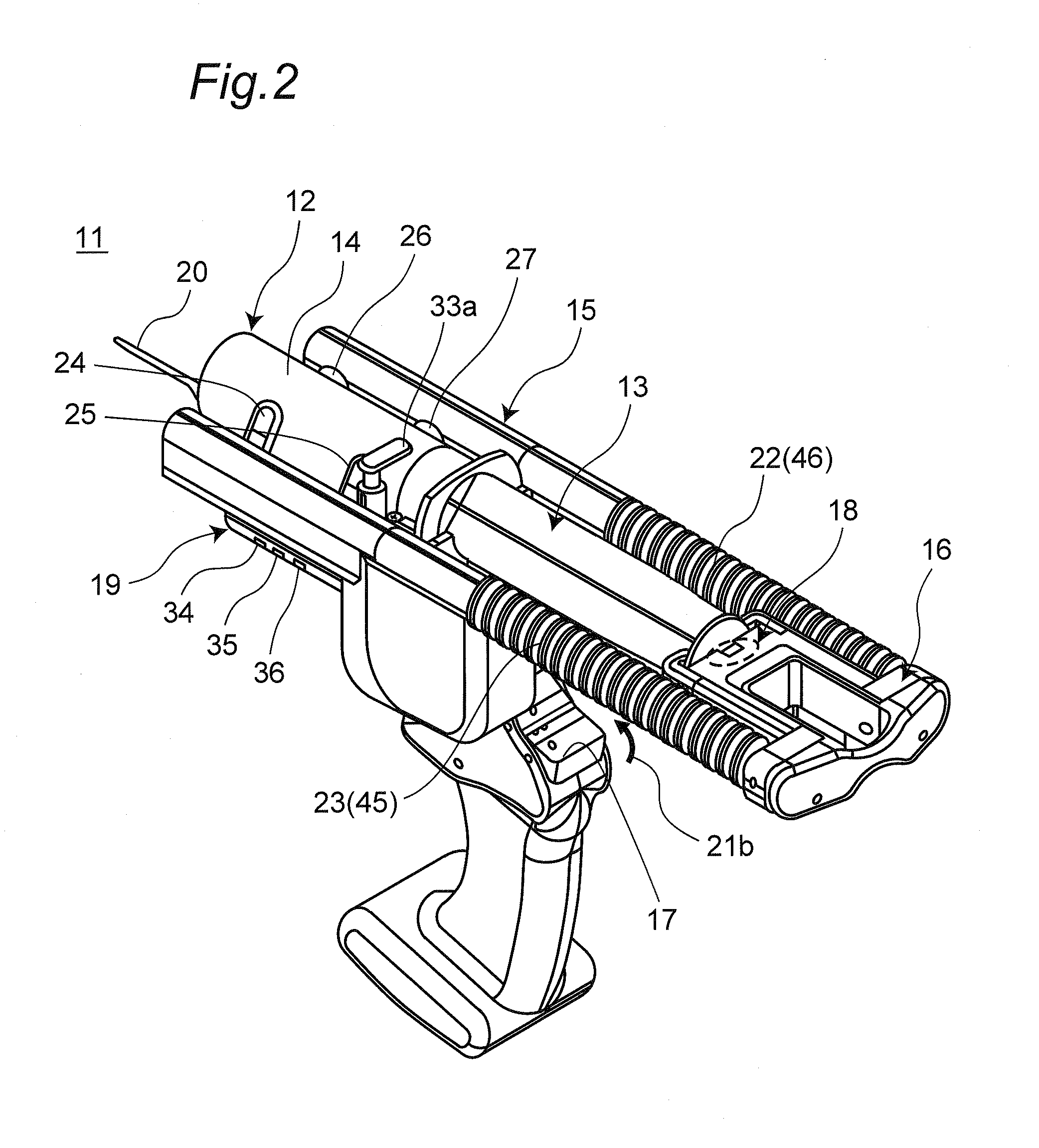
[0042]FIGS. 1 to 3 each show a syringe drive device 11 according to the present first embodiment. The syringe drive device 11 assists in pushing and pulling a plunger 13 of a syringe 12 with respect to an outer tube 14.

[0043]The syringe drive device 11 includes a fixing section 15 that fixes the outer tube 14 of the syringe 12, a holder 16 that holds the plunger 13 of the syringe 12, and a drive section 42 (shown in FIG. 3 as a pattern view) which linearly moves the holder 16 along an axis of the plunger 13. The fixing section 15 is provided therebelow with a grip section 30 that extends downward and is to be held by an operator with a hand.

[0044]The syringe 12 is mounted on the fixing section 15 of the syringe drive device 11 such that a flange 31 of the outer tube 14 is fitted in a recess of a flange accommodation section 28 and a press section (brim section) 32 provided at an end of the plunger 13 is fitted in a recess 29 provided in a front portion of the holder 16. Then, a shaf...

second embodiment

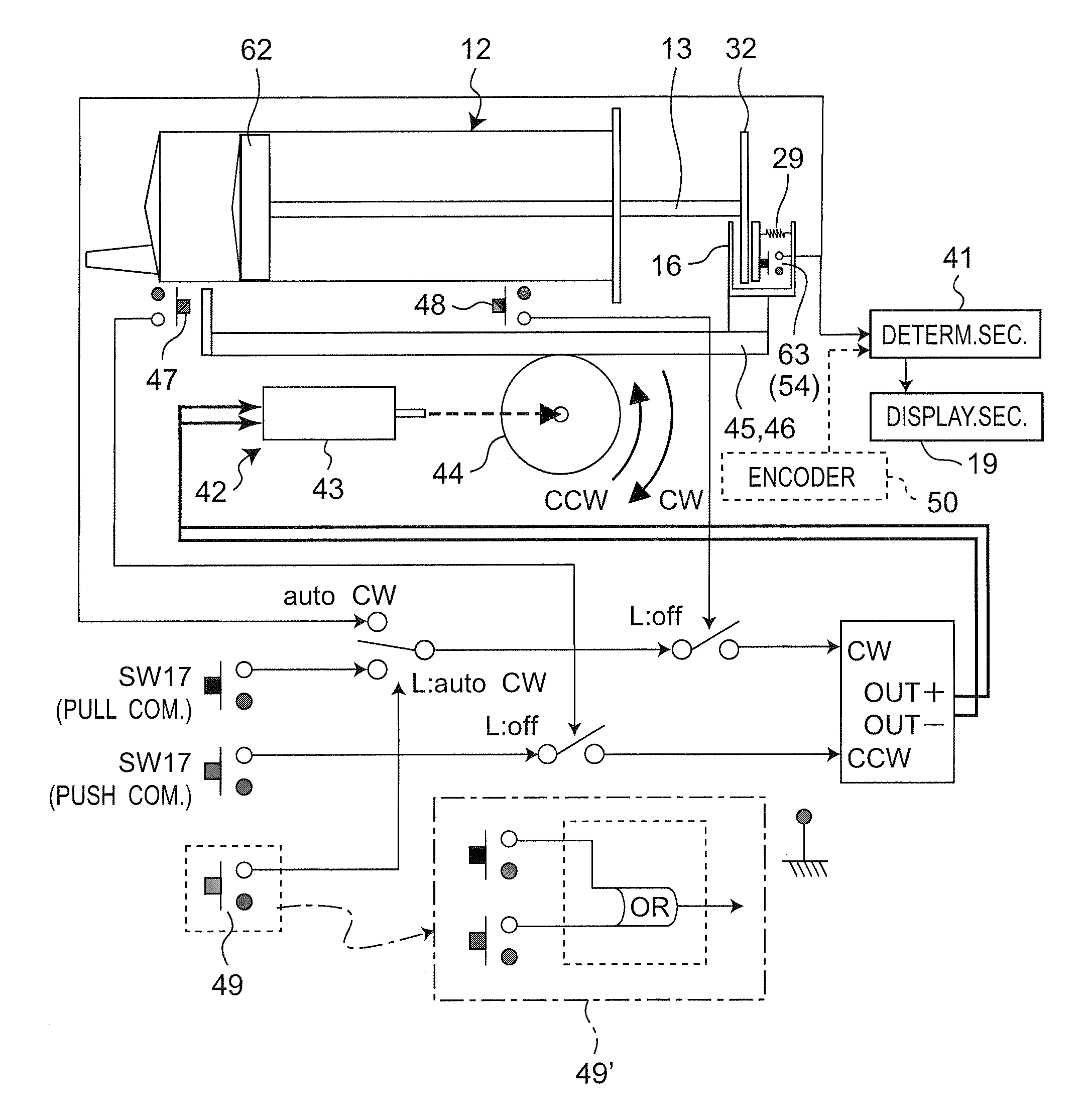
[0097]A syringe drive device 11 shown in FIGS. 9 to 12 according to a second embodiment is different from that of the first embodiment, in that it is possible to adjust the force for pressing the plunger 13 so as to be pushed by means of the movable section 58 of the internal pressure detector 18 using the bias force of the bias spring 53.

[0098]The syringe frictional force is varied in accordance with the size of the gasket 62, in other words, the content of the syringe to be used. The force for pushing the plunger 13 by means of the movable section 58 using the bias spring 53 is adjustable in correspondence with the syringe 12 to be used. Therefore, even though the syringe has a different content, it is possible to appropriately eliminate or reduce the influence of the frictional force and calculate the internal pressure of the syringe 12 with a high degree of accuracy in accordance with the state of the positive pressure detection switch 63 or the detection value of the force sens...


PUM


Abstract

A syringe drive device 11 includes a fixing section 15 fixing an outer tube 14, a movable holder 16 holding a plunger 13, and a drive section 42 driving the holder 16 along an axis of the plunger to push and pull the plunger with respect to the outer tube 14. An internal pressure detector 18 has a positive pressure detection switch 63 detecting an internal pressure of a syringe 12. A determination section 41 determines issue of an alert when the holder 16 is stopped and the positive pressure detection switch 63 is ON. A display section 19 is lit to indicate the alert when the determination section 41 determines issue of the alert.

Description

TECHNICAL FIELD[0001]The present invention relates to a syringe drive device for driving a syringe by pushing and pulling a plunger of the syringe.BACKGROUND ART[0002]In cases of performing medicinal solutions mixing operations in hospitals, such as preparing infusion medicinal solutions, it has been well known that a plurality of medicinal solutions filled respectively in medicine bottles called vials are aspirated by means of a syringe and are mixed in this syringe to prepare the infusion medicinal solutions. The medicinal solutions thus prepared are then discharged from the syringe so as to be filled into an infusion bag or the like.[0003]In such medicinal solution mixing operations performed in hospitals, there are cases where a large amount of a medicinal solution of high viscosity, such as dextrose in water in high concentration, is dealt with use of a syringe of a large content of about 50 ml, for example. In these cases, there needs quite a large force of more than one hundr...

Claims


Application Information

Patent Timeline
Patent Type & Authority Applications(United States)
IPC IPC(8): G08B21/18
CPCA61M5/1456A61M5/16854A61M2202/049A61M2205/3331A61M2205/18A61M2205/332A61M5/1458
Inventor FUJIOKA, SOICHIRONAKAMURA, TOHRUMIZUNO, OSAMUOKUDA, AKINOBUOHTA, AKIHIRO
Owner PANASONIC CORP
Why Eureka
Try Eureka