Liquid ejecting head and liquid ejecting apparatus

Inactive Publication Date: 2012-11-29
SEIKO EPSON CORP
View PDF11 Cites 4 Cited by
  • Summary
  • Abstract
  • Description
  • Claims
  • Application Information

AI Technical Summary

Benefits of technology

[0019]According to the aspect of the invention, the liquid ejecting head in which dimensions of the individual flow pat

Problems solved by technology

However, if flow paths and the like are formed on the flow path formation substrate, the vibration plate, and the pressure generation chamber bottom plate, they are individually calcined, and then the calcined members are bonded to one another, there arises the following problem.
That is, a problem that positional deviation or deviation in pitch is generated due to fluctuation in contraction by the calcination arises.
However, in an ink jet recording head obtained in such a manner that after the individual flow paths such as the pressure generation chambers have been formed on the flow path formation substrate, a first member as the vibration plate and a second member as the pressure generation chamber bottom plate are bonded to the flow path formation substrate and they are calcined at the same time so as to be integrated with one another, there is the following probl

Method used


Image

  • Liquid ejecting head and liquid ejecting apparatus
  • Liquid ejecting head and liquid ejecting apparatus
  • Liquid ejecting head and liquid ejecting apparatus

Examples


first embodiment

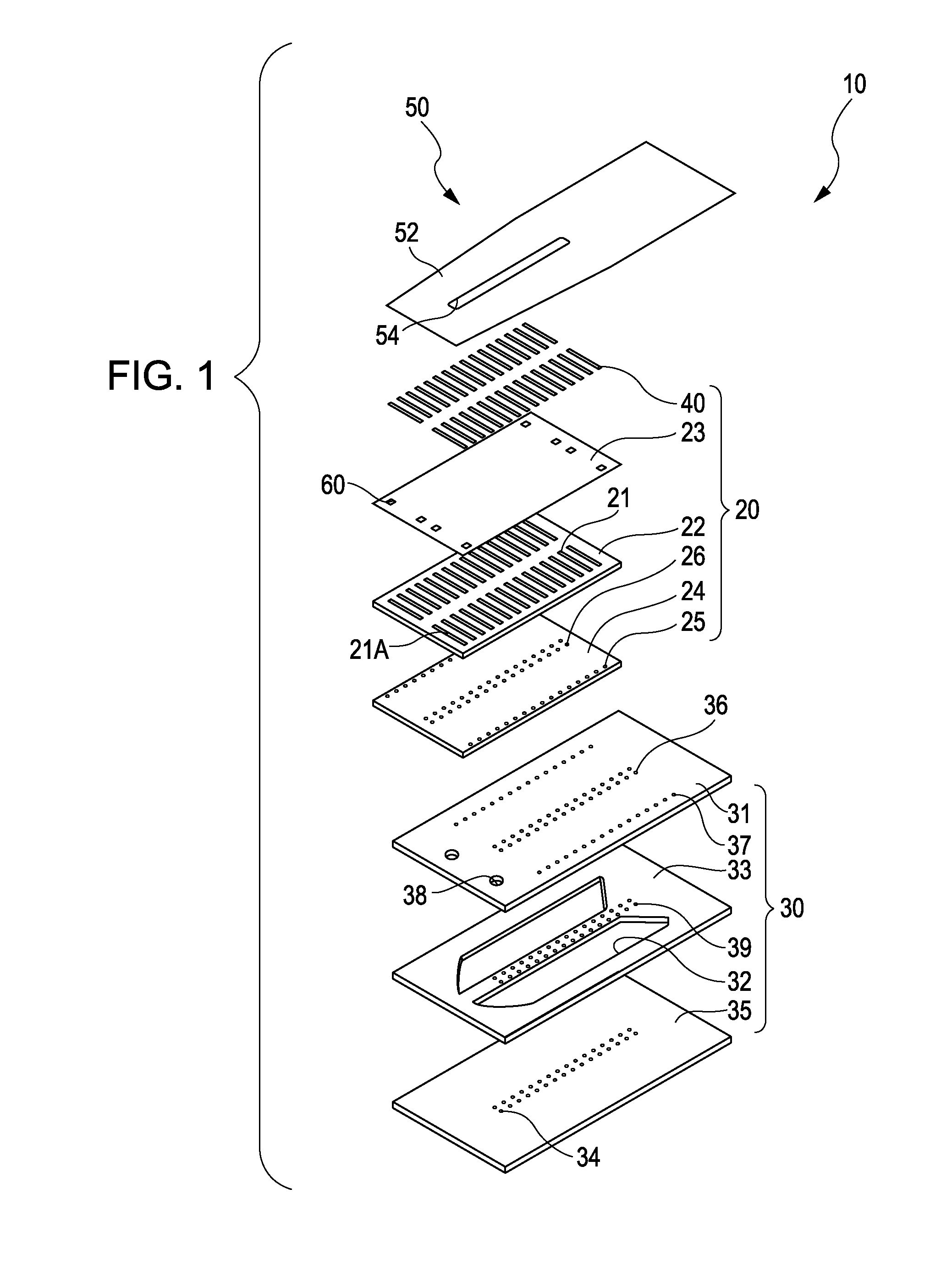
[0029]FIG. 1 is an exploded perspective view illustrating an ink jet recording head as an example of a liquid ejecting head according to the first embodiment of the invention.

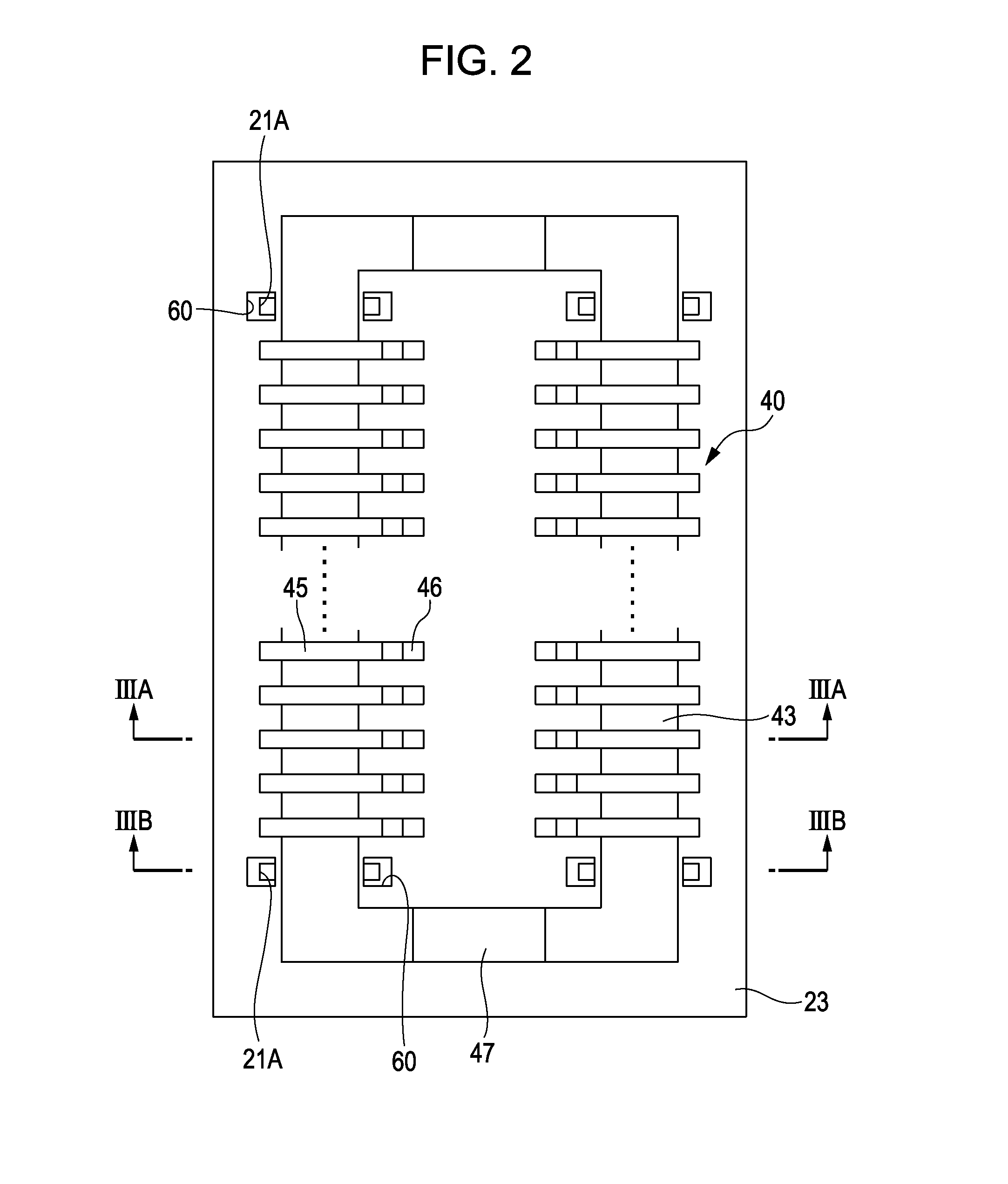
[0030]FIG. 2 is a plan view illustrating an actuator unit of the ink jet recording head. FIGS. 3A and 3B are a cross-sectional view cut along a line IIIA-IIIA of FIG. 2 and a cross-sectional view cut along a line IIIB-IIIB of FIG. 2.

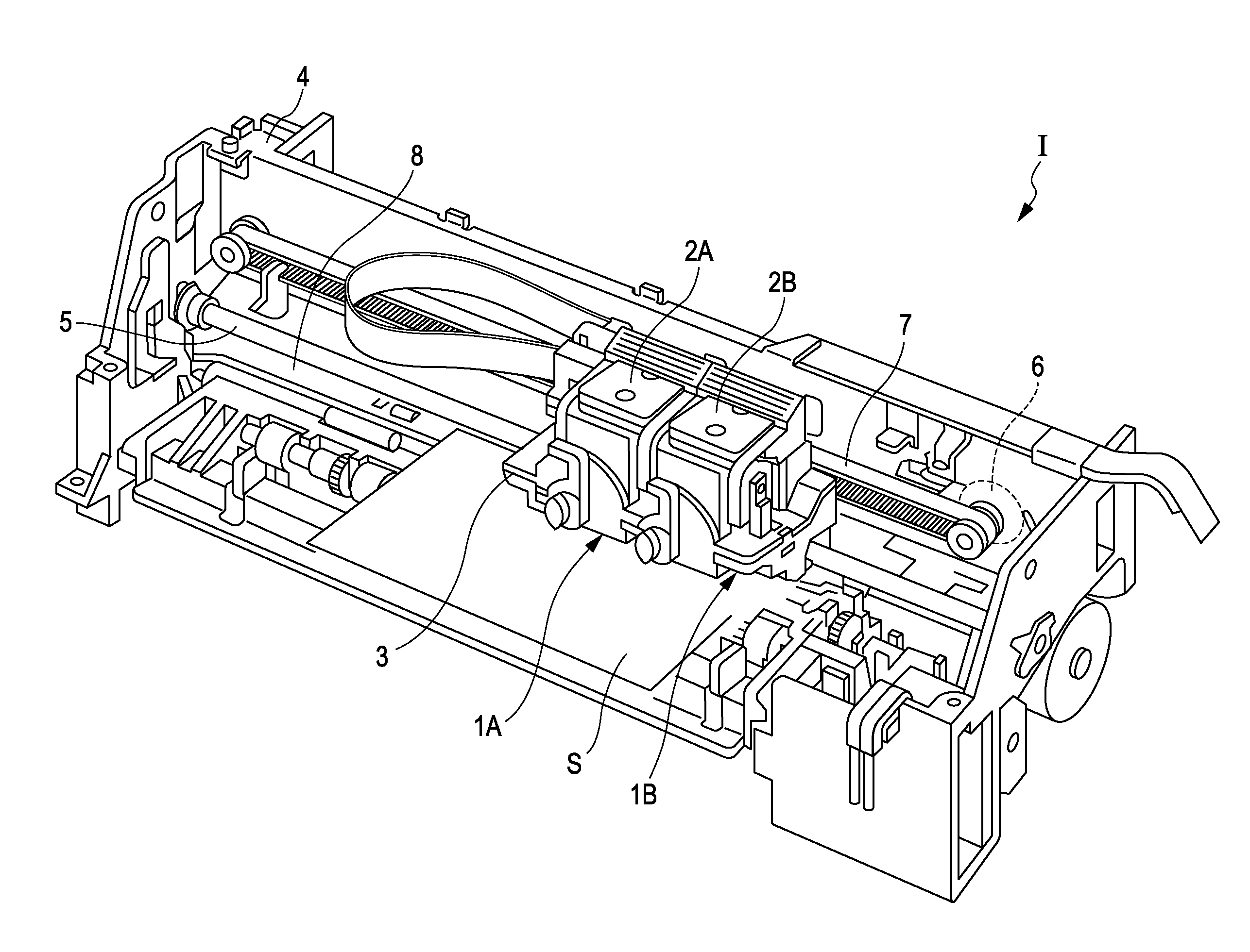
[0031]As illustrated in the drawings, an ink jet recording head 10 according to the embodiment includes an actuator unit 20, one flow path unit 30 to which the actuator unit 20 is fixed, and a wiring substrate 50 which is connected to the actuator unit 20.

[0032]The actuator unit 20 is an actuator device including piezoelectric actuators 40 as a pressure generation unit. The actuator unit 20 includes a flow path formation substrate 22, a vibration plate 23, and a pressure generation chamber bottom plate 24. Pressure generation chambers 21 are formed on the flow path formation substra...


PUM


Abstract

A liquid ejecting head includes a flow path formation substrate on which individual flow paths communicating with nozzle openings for ejecting liquid are provided, a first member which is provided at one surface side of the flow path formation substrate and has pressure generation units for generating pressure change in liquid in the individual flow paths, and a second member which is provided at a surface side of the flow path formation substrate, which is opposite to the first member. Dummy flow paths are provided on the flow path formation substrate independently of the individual flow paths. Exposure portions which expose a part of wall surfaces of the flow path formation substrate which form the dummy flow paths, are provided at least one of the first member and the second member.

Description

BACKGROUND[0001]1. Technical Field[0002]The present invention relates to a liquid ejecting head and a liquid ejecting apparatus which eject liquid through nozzle openings, in particular, relates to an ink jet recording head and an ink jet recording apparatus which eject ink as liquid.[0003]2. Related Art[0004]As an ink jet recording head as an example of a liquid ejecting head, there is the following ink jet recording head, for example. That is, there is an ink jet recording head which includes an actuator unit on which piezoelectric elements and pressure generation chambers are provided, and a flow path unit having a nozzle plate provided with nozzle openings which communicate with the pressure generation chambers and through which ink droplets are discharged.[0005]The actuator unit is configured by laminating a flow path formation substrate on which the pressure generation chambers are formed, a vibration plate which is provided at one surface side of the flow path formation subst...

Claims


Application Information

Patent Timeline
IPC IPC(8): B41J2/135B41J2/015
CPCB41J2/14233B41J2/1632B41J2/1623B41J2/161
Inventor MUNAKATA, MANABUOKAZAWA, NORIAKI
Owner SEIKO EPSON CORP
Why Eureka
Try Eureka