Liquid crystal plate, liquid crystal injection apparatus and liquid crystal injection method

Inactive Publication Date: 2008-07-31
NEC LCD TECH CORP
View PDF0 Cites 5 Cited by
  • Summary
  • Abstract
  • Description
  • Claims
  • Application Information

AI Technical Summary

Benefits of technology

[0023]The provision of the ribs (raised members) acting as banks for the raised portions of the liquid crystal material at both ends of the recess in the liquid crystal plate or the baffle structure having a baffle acting as a shielding plate at each end of the recess helps to achieve uniform liquid crystal characteristics of a plurality of liquid crystal panels that are fabricated simultaneously by maintaining volatile amount of liquid crystal material to be injected into the liquid crystal panels (liquid crystal cells) constant regardless of their locations to be set to the liqui

Problems solved by technology

This means that longer time is required for evacuating the evacuation container, thereby some compositions in the liquid crystal material tend to evaporate and significantly deteriorating liquid crystal performances such as response time and the like of the fabricated liquid crystal display devices.
Moreover, even if the degree of vacuum may be optimized, it is impossible to improve uniformity of the fabricated liquid crystal panels due to locations of the liquid crystal panels that are set in the evacuation container or the liquid crystal plate.
However, the liquid crystal injection method as disclosed in the Patent Document 2 encounters the following problems:
A first problem is that additional supplementary liquid crystal material must be prepared and placed in the evacuation container.
A secon

Method used


Image

  • Liquid crystal plate, liquid crystal injection apparatus and liquid crystal injection method
  • Liquid crystal plate, liquid crystal injection apparatus and liquid crystal injection method
  • Liquid crystal plate, liquid crystal injection apparatus and liquid crystal injection method

Examples


Embodiment Construction

[0037]Now, exemplary embodiments of the liquid crystal plate, the liquid crystal injection apparatus and the liquid crystal injection method according to the present invention will be described hereunder in detail with reference to the accompanying drawings.

Features of the Present Invention

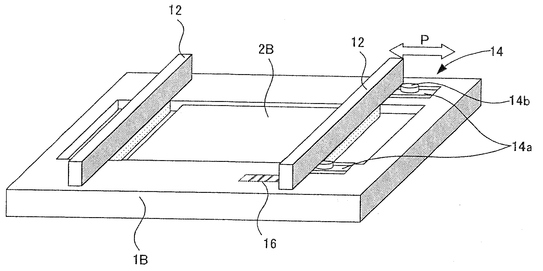
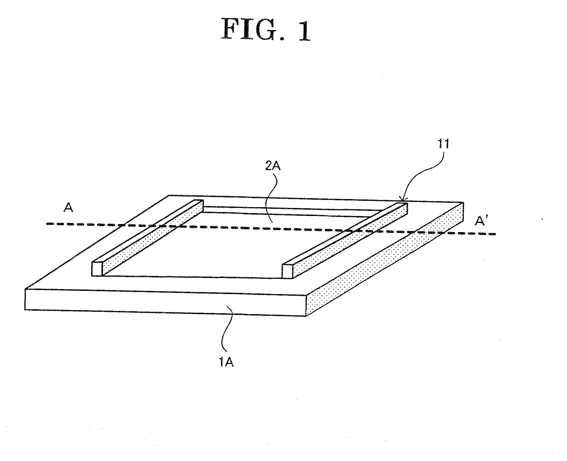
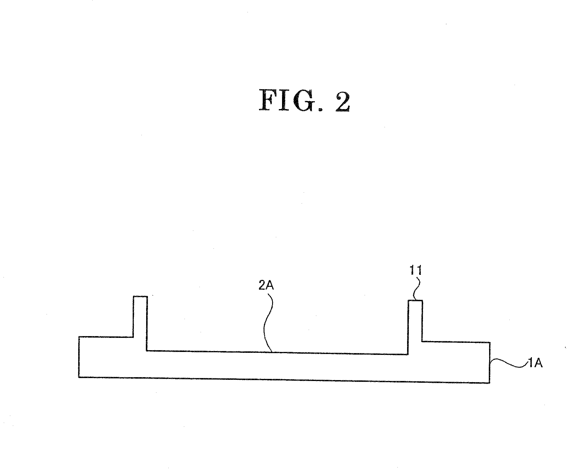
[0038]Features of the present invention will be described before giving detailed description. Raised members such as a rib structure or a baffle structure are provided at both end portions of the recess in the liquid crystal plate. Even if highly volatile liquid crystal material may be used, the raised members (i.e., the rib structure or the baffle structure) help to uniformly inject such liquid crystal material into a plurality of liquid crystal panels constituting a cassette regardless of the location of each liquid crystal panel. Moreover, it is also possible to provide the liquid crystal plate that reduces volatile amount of the liquid crystal material.

Construction of the Exemplary Embodiments...


PUM


Abstract

A liquid crystal plate for storing a liquid crystal material for simultaneously injecting it into a plurality of liquid crystal panels and liquid crystal injection apparatus and method using such liquid crystal plate are disclosed. The liquid crystal plate has a recess for storing the liquid crystal material and a pair of raised members such as ribs, baffles or the like at both end portions of the recess in parallel with the outermost liquid crystal panels. The raised members have the height at least equal to the top surface of the liquid crystal material filled in the recess for maintaining the liquid crystal characteristics of the liquid crystal material injected into the plurality of liquid crystal panels substantially uniform regardless of the location in a cassette.

Description

INCORPORATION BY REFERENCE[0001]This application is based upon and claims the benefit of priority from Japanese patent application no. 2007-018121, the disclosure of which is incorporated herein in its entirety by reference.FIELD OF INVENTION[0002]The present invention relates to a liquid crystal plate, a liquid crystal injection apparatus and a liquid crystal injection method, more specifically to a liquid crystal plate having a recess to store a liquid crystal material for simultaneously injecting it into a plurality of liquid crystal panels in a cassette and liquid crystal injection apparatus and method that use such liquid crystal plate suitable for simultaneously injecting a liquid crystal material of uniform composition into a plurality of liquid crystal panels.RELATING ART[0003]A liquid crystal display device is fabricated by assembling a liquid crystal panel (or a liquid crystal cell) that comprises a pair of substrates having electrodes and an orientation film formed on the...

Claims


Application Information

Patent Timeline
IPC IPC(8): G02F1/1341
CPCG02F1/1341G02F1/1303
Inventor IIO, TERUNOBUKONDO, TAKANORI
Owner NEC LCD TECH CORP
Why Eureka
Try Eureka