Acousto-optic imaging system, and acousto-optic imaging apparatus

Inactive Publication Date: 2014-01-09
PANASONIC INTELLECTUAL PROPERTY MANAGEMENT CO LTD
View PDF0 Cites 2 Cited by
  • Summary
  • Abstract
  • Description
  • Claims
  • Application Information

AI Technical Summary

Benefits of technology

[0013]The ultrasonograph shown in FIG. 13 enables flexible imaging. This ultrasonograph, however, requires many iterations of a signal process (delay synthesis) for obtaining a single ultrasonic image. The required number of iterations of the signal process is at least equivalent to the number of pixels of the image. Therefore, to realize high-speed ultrasonic imaging, there will be a n

Problems solved by technology

This ultrasonograph, however, requires many iterations of a signal process (delay synthesis) for obtain

Method used


Image

  • Acousto-optic imaging system, and acousto-optic imaging apparatus
  • Acousto-optic imaging system, and acousto-optic imaging apparatus
  • Acousto-optic imaging system, and acousto-optic imaging apparatus

Examples


Example

[0069]First, a first embodiment of the present invention will be described.

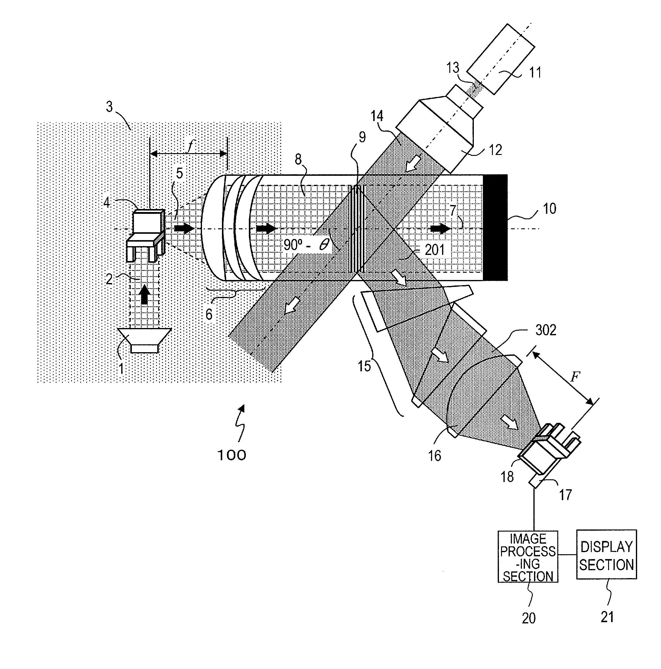
[0070]FIG. 1 is a diagram schematically showing a configuration of an acousto-optic imaging system 100 according to a first embodiment of the present invention. The acousto-optic imaging system 100 includes an ultrasonic wave source 1, an acousto-optic medium 8, an acoustic lens 6 arranged on one surface of the acousto-optic medium 8 that is closer to an imaged object 4, a sound wave absorbing end 10 arranged on one surface of the acousto-optic medium 8 opposite to the surface on which the acoustic lens 6 is arranged, a monochromatic light source 11, a beam expander 12, a distortion compensation section 15, an image-forming lens 16, and an image-receiving section 17. Note that the imaged object 4 and an image 18 shown in FIG. 1 are not components of the acousto-optic imaging system 100, but are shown for the purpose of illustration.

[0071]The ultrasonic wave source 1, the acoustic lens 6, a portion of the acou...

Example

[0133]Next, a second embodiment of the present invention will be described.

[0134]FIG. 8 is a diagram showing a configuration of an acoustic lens 60 in an acousto-optic imaging system 200 of the present embodiment. The only difference between the acousto-optic imaging system 200 of the present embodiment and the acousto-optic imaging system 100 of Embodiment 1 is the configuration of the acoustic lens. Therefore, components other than the acoustic lens 60 of the acousto-optic imaging system 200 will not be described below.

[0135]In the acousto-optic imaging system 100 of Embodiment 1, the acoustic lens 6 and the acousto-optic medium 8 are all formed by a silica nano porous material. It has been stated that the sonic speed of the silica porous material can be varied over a wide range by adjusting the condition for producing a silica nano porous material. Thus, using a silica nano porous material as the acoustic lens 6 allows for a flexible acoustic medium selection. As with ordinary op...

Example

[0141]Next, a third embodiment of the present invention will be described.

[0142]FIG. 9 is a diagram showing a configuration example of the distortion compensation section 15 in an acousto-optic imaging system of the present embodiment. The only difference between the present embodiment and Embodiments 1 and 2 is the configuration of the distortion compensation section 15. Therefore, components other than the distortion compensation section 15 will not be described below.

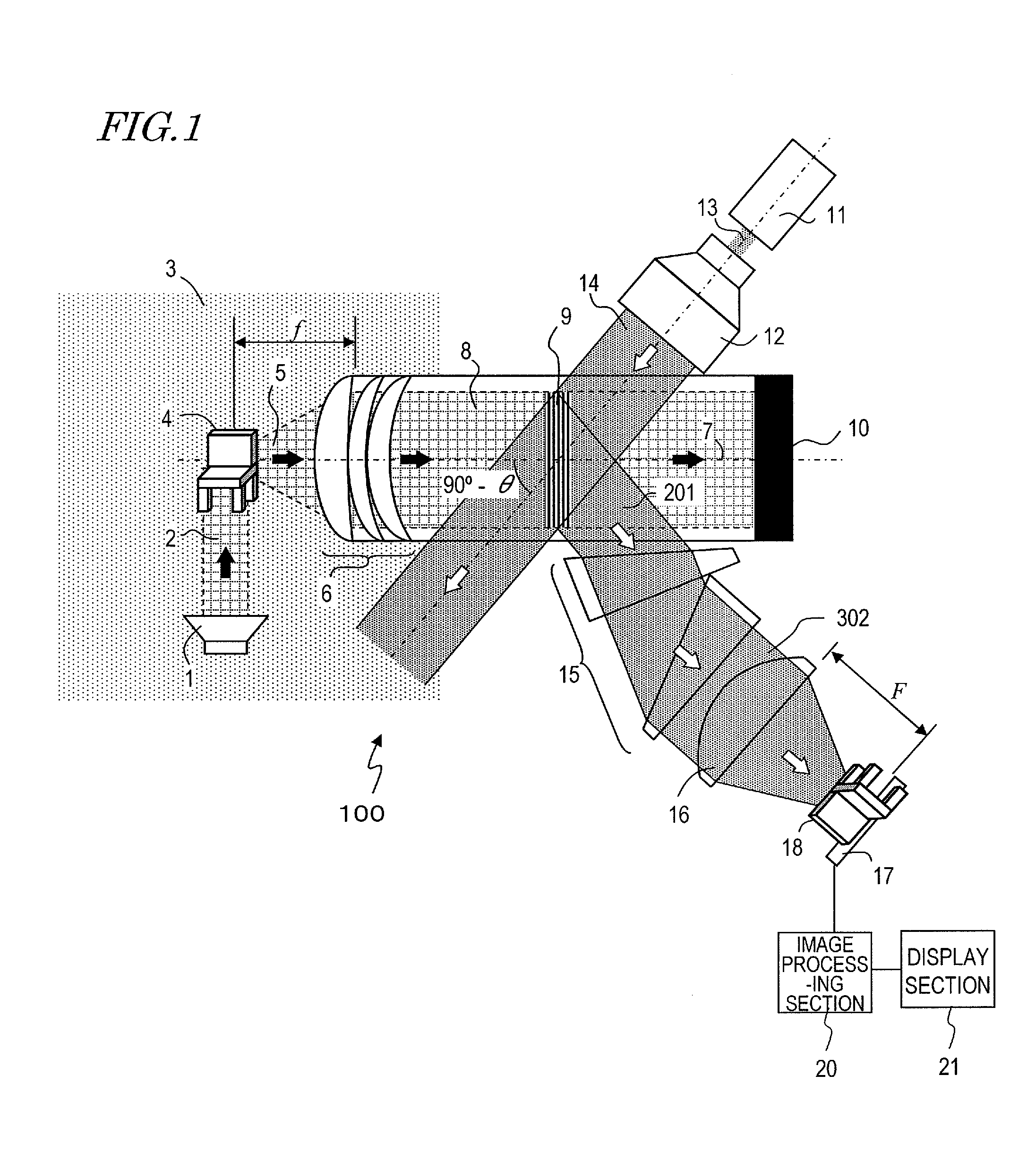
[0143]As shown in FIG. 3, where the diffraction angle is θ, the diffraction light 201 generated by Bragg diffraction is contracted by a factor of sine in a direction parallel to the drawing sheet of FIG. 3 (the y-axis direction). Therefore, if the diffraction light 201 is imaged by the image-forming lens 16 as it is, the image 18 is distorted, and it is not possible to obtain an image similar to the imaged object 4. In order to solve this problem, the function of the distortion compensation section 15 was to change t...


PUM


Abstract

An acousto-optic imaging system includes: an ultrasonic wave source for irradiating an imaged object with an ultrasonic wave; an acoustic lens for converting a scattered wave of the ultrasonic wave to a plane wave; a light-transmitting acoustic medium provided in an area on an opposite side of the imaged object with respect to the acoustic lens; a light source for outputting a monochromatic light plane wave; an image-forming lens arranged so as to condense diffraction light of the monochromatic light plane wave which is produced in the light-transmitting acoustic medium; an image-receiving section for obtaining an optical image formed by the image-forming lens; and a distortion compensation section for correcting a distortion of the optical image or a distortion.

Description

[0001]This is a continuation of International Application No. PCT / JP2012 / 003754, with an international filing date of Jun. 8, 2012, which claims priority of Japanese Patent Application No. 2011-135259, filed on Jun. 17, 2011, the contents of which are hereby incorporated by reference.BACKGROUND[0002]1. Technical Field[0003]The present application relates to an acousto-optic imaging system, in which an imaged object is irradiated with an ultrasonic wave and the ultrasonic wave scattered by the imaged object is introduced into an acousto-optic medium, thus forming a refractive index distribution across the acousto-optic medium, thereby causing Bragg diffraction, which is used to map the intensity / phase distribution of the scattered ultrasonic wave onto an intensity / phase distribution of monochromatic light, thus obtaining an ultrasonic image as an optical image.[0004]2. Description of the Related Art[0005]Ultrasonographs are known in the art as an apparatus for irradiating an imaged o...

Claims


Application Information

Patent Timeline
IPC IPC(8): G01N29/04
CPCG01N29/04G01N29/221G01N29/2418A61B5/0097G01N29/0681G01N29/46
Inventor SANGAWA, USHIOIWAMOTO, TAKUYAKANEKO, YURIKOHASHIMOTO, MASAHIKO
Owner PANASONIC INTELLECTUAL PROPERTY MANAGEMENT CO LTD
Why Eureka
Try Eureka