Modular it rack cooling assemblies and methods for assembling same

a technology of cooling assembly and server rack, applied in the field of computing or information technology (it) data centers, can solve the problems of increasing the total power consumption and total heat output of the server rack and the server rack assembly in the data center, the cooling system of the computer server rack has been struggling to keep pace, and the latest designs are limited in their ability to scale up to the cooling requirements of increasingly high density data centers

Inactive Publication Date: 2012-11-29
INERTECH IP
View PDF16 Cites 81 Cited by
  • Summary
  • Abstract
  • Description
  • Claims
  • Application Information

AI Technical Summary

Problems solved by technology

The expansion of server capabilities has led to an increase in total power consumption and total heat output per server and per server rack assembly in data centers.
Cooling systems for computer server racks have been struggling to keep pace with the ability to cool ever increasing computer server heat loads in data centers.
The latest designs are limited in their ability to be scaled to cooling requirements of increasingly high density data centers.
The output capacity of rear-door exchangers is limited to the physical size of the computer rack exterior perimeter and the amount of fluid (measured in gallons per minute (gpm)) that can be applied to a rear-door exchanger without excessive pressure drops.
Therefore, the total capacity is limited to the physical size of the coils as well as the size of the enclosure for the computer server racks.
The rear-door heat exchangers and other similar cooling products on the market cannot handle the cooling requirements of these high-density computer servers.
These data centers, however, waste a significant amount of space.
Also, it is difficult to increase the cooling capacity of the in-row rack cooling systems when servers are added to the server racks or existing servers are replaced with servers requiring more cooling capacity.
Furthermore, it is difficult for many existing data centers to upgrade their cooling systems to comply with future government regulations that require reductions in energy consumption.

Method used


Image

  • Modular it rack cooling assemblies and methods for assembling same
  • Modular it rack cooling assemblies and methods for assembling same
  • Modular it rack cooling assemblies and methods for assembling same

Examples


Embodiment Construction

[0044]Embodiments of the presently disclosed heat exchanger support structures, heat exchanger support systems and installation methods will now be described in detail with reference to the drawings, in which like reference numerals designate identical or corresponding elements in each of the several views.

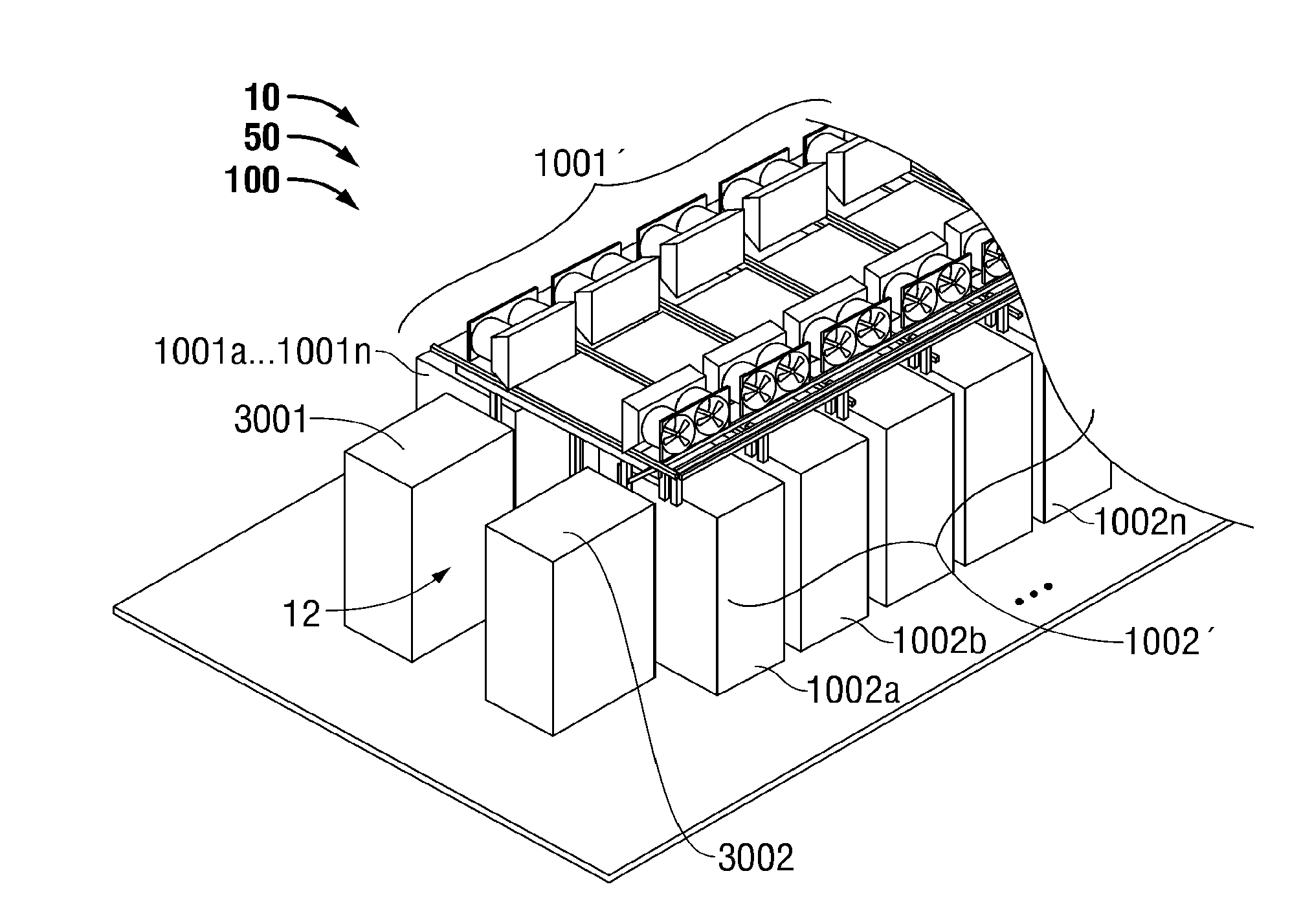
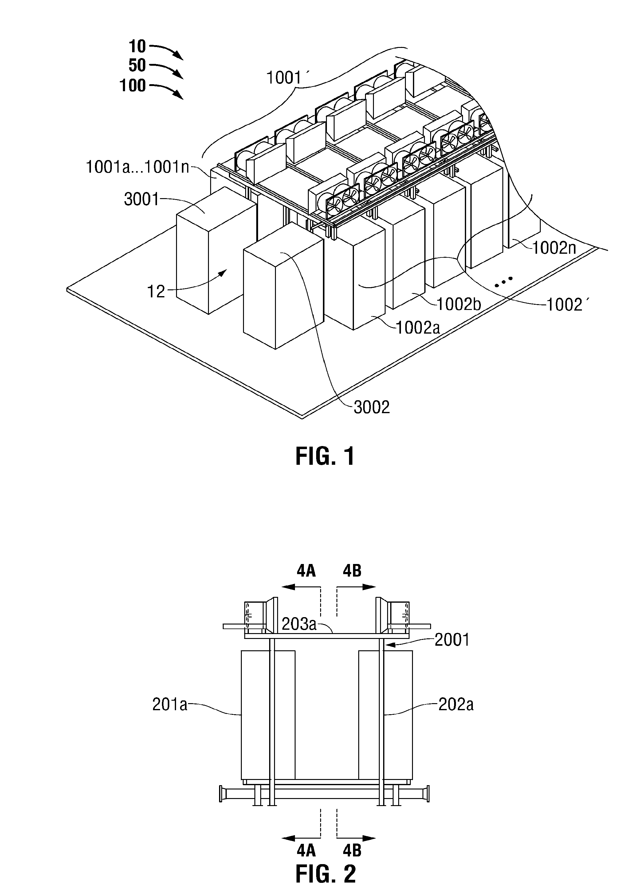
[0045]The presently disclosed heat exchanger support structures, heat exchanger support systems and installation method advance the state of the art of data center cooling by providing additional cooling capacity within the same floor space of an existing or planned data center, thus reducing the cooling capacity foot print of the data center and increasing the cooling capacity per unit area. The presently disclosed heat exchanger support structures, heat exchanger support systems and installation method can be retrofitted into existing data centers or planned as part of new installations.

[0046]FIG. 1 illustrates a modular unified racking system installation 100 for IT servers in ...


PUM

PropertyMeasurementUnit
temperatureaaaaaaaaaa
condensing temperatureaaaaaaaaaa
temperatureaaaaaaaaaa

Abstract

A modular server rack cooling structure for cooling at least one server in at least one server rack of a data center assembly includes at least a first supporting member and at least a first heat exchanger. The first heat exchanger is coupled to the first supporting member, which is configured to position the first heat exchanger in heat transfer relationship with the at least one server. The first heat exchanger is not attached to the at least one server rack. The modular server rack cooling structure is also applied to a system that includes at least a first rack and at least a second rack disposed opposite from one another to form a hot aisle or a cold aisle. A method is disclosed for installing additional heat exchangers on the support structure of a modular server rack cooling structure to meet increased cooling capacity requirements without requiring additional space.

Description

CROSS-REFERENCE TO RELATED APPLICATIONS[0001]This application relates to International Application No. PCT / US2011 / 41710, which was filed on Jun. 23, 2011, and claims the benefit of, and priority to, U.S. Provisional Patent Application No. 61 / 448,631, which was filed on Mar. 2, 2011; and U.S. Provisional Patent Application No. 61 / 482,070, which was filed on May 3, 2011, the entire contents of each of which are hereby incorporated by reference herein.BACKGROUND[0002]1. Technical Field[0003]The present disclosure generally relates to computing or information technology (IT) data centers. More particularly, the present disclosure relates to structures, systems and methods for installing heat exchangers in IT data centers.[0004]2. Background of Related Art[0005]Over the past several years, computer equipment manufacturers have expanded the data collection and storage capabilities of their servers. The expansion of server capabilities has led to an increase in total power consumption and ...

Claims


Application Information

Patent Timeline
Patent Type & Authority Applications(United States)
IPC IPC(8): G06F1/20H05K7/20B23P11/00H05K7/18
CPCY10T29/49826H05K7/20745H05K7/20H05K7/20736H05K7/20781H05K7/20827
Inventor KEISLING, EARLCOSTAKIS, JOHNMCDONALD, GERALD
Owner INERTECH IP
Why Eureka
Try Eureka