Method of manufacturing a wheel rim for a vehicle

a manufacturing method and technology for vehicles, applied in the direction of manufacturing tools, transportation and packaging, metal rolling arrangements, etc., can solve the problems of non-constant thickness of vehicle wheel rims, high cost of flow-forming equipment, and difficulty in forming at successive steps, so as to achieve the effect of being more resistant to being drawn and being easy to form at the subsequent steps

Active Publication Date: 2012-12-06
TOPY INDUSTRIES
View PDF4 Cites 6 Cited by
  • Summary
  • Abstract
  • Description
  • Claims
  • Application Information

AI Technical Summary

Benefits of technology

[0014]According to the method of manufacturing a wheel rim for a vehicle according to item (1) above, since the tubular material is formed into the tubular member having a non-constant thickness by ironing, an equipment and a step of the conventional flow-forming may be unnecessary. As a result, the above-described problems (i), (ii) and (iii) existing in the flow-forming may be solved as the following ways (i), (ii) and (iii), respectively:
[0015]According to the method of manufacturing a wheel rim for a vehicle according to item (2) above, since the flange portion of the tubular material has one or more axially intermediate bent portions, even if the bending angles of the bent portion and the axially intermediate bent portions are small, the tubular material may be more resistant to being drawn into the die by the punch and moved relative to the die than in a case where the flange portion of the tubular material does not have axially intermediate bent portions. Further, when the bending angles are small, forming at succeeding steps may be easy.
[0016]According to the method of manufacturing a wheel rim for a vehicle according to item (3) above, since a bending direction of at least one of the one or more axially intermediate bent portions and a bending direction of the bent portion are opposite to each other, a portion of the flange portion of the tubular material located on a tip side of the axially intermediate bent portion whose bending direction is opposite to the bending direction of the bent portion may engage with the pressing member, whereby the tubular material may be more resistant to being drawn into the die by the punch and m

Problems solved by technology

However, there are the following problems with the manufacturing method of the vehicle wheel rim having a non-constant thickness using flow-forming:
(i) The equipment used in the flow-forming may be expensive.
In flow-forming, since a roll for pressing the tubular material to a mandrel may be moved in two directions, an axial direction of the material and a thickness direction of the material, the flow-forming equipment may be expensive multiple times as comp

Method used


Image

  • Method of manufacturing a wheel rim for a vehicle
  • Method of manufacturing a wheel rim for a vehicle
  • Method of manufacturing a wheel rim for a vehicle

Examples


first embodiment

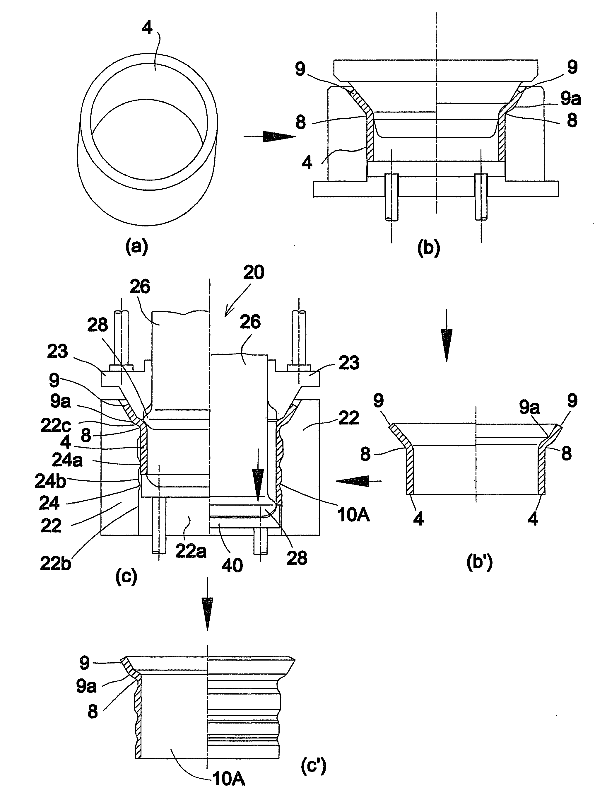
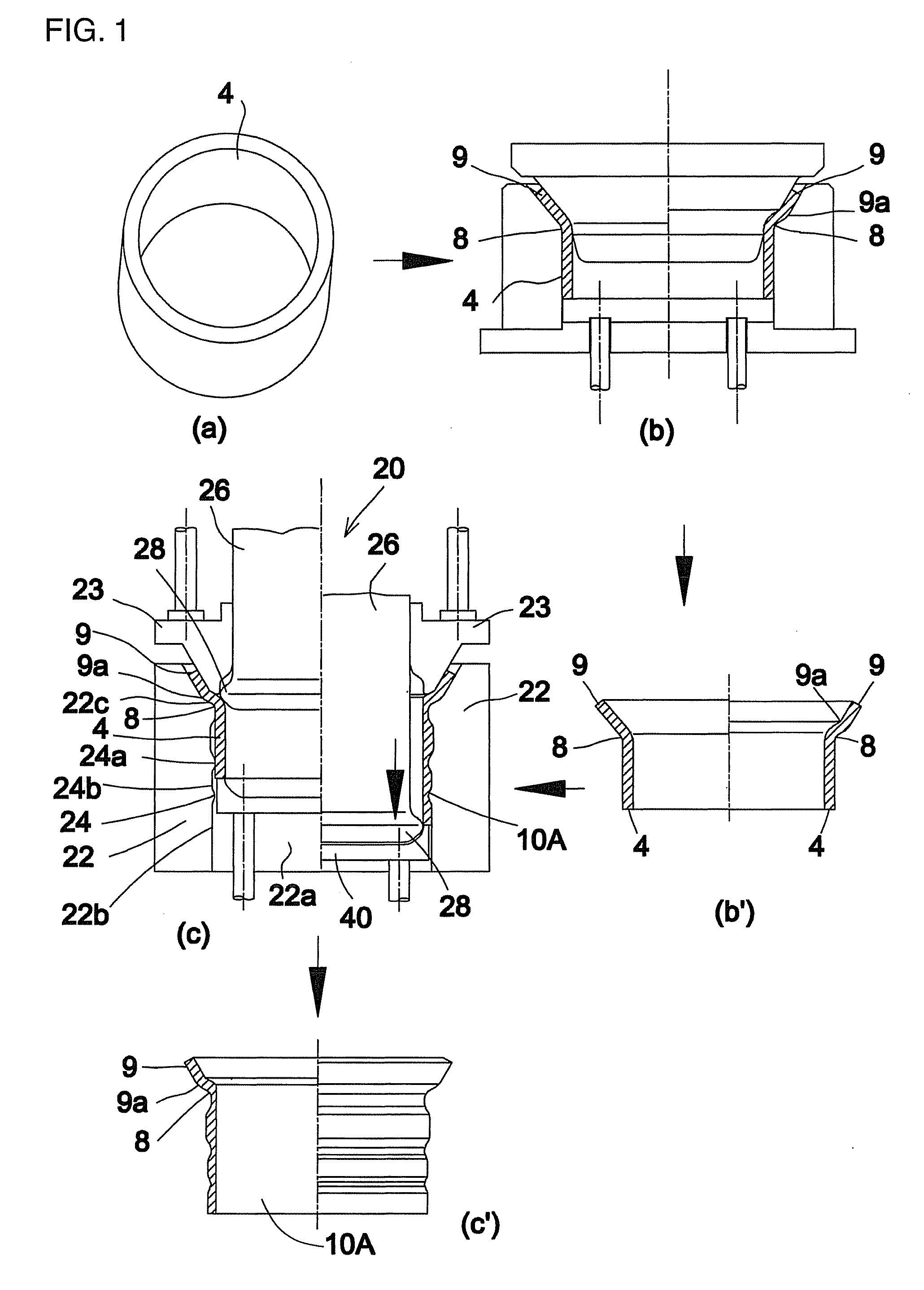
[0093]In the method of manufacturing the wheel rim 10B for a vehicle according to the first embodiment of the present invention, as illustrated in (c) of FIG. 1 and FIG. 6, the die 22 may be constructed of an outer die having a cylindrical bore 22a and an inner side surface 22b. The inner side surface 22b of the outer die may form the convex and concave surface 24. The punch 26 may be constructed of an inner punch which moves into or out from the cylindrical bore 22a of the outer die 22 in the axial direction of the cylindrical bore. The protrusion 28 may be formed at an outside surface 26e of the inner punch. The flange portion of the tubular material 9 may be bent outwardly in the radial direction of the tubular material 4.

[0094]As illustrated in FIG. 6, a flange receiving portion 22c, with which the flange portion of the tubular material 9 engages, may be formed at an upper end portion of the inner side surface 22b of the outer die 22. The tubular material 4 may be set to the out...

second embodiment

[0098]In the method of manufacturing the tubular member 10 according to the second embodiment of the present invention, as illustrated in FIGS. 11 and 12, the die 22 may be constructed of an inner die having an outer side surface 22e. The outer side surface 22e of the inner die 22 may be constructed to be the convex and concave surface 24. The punch 26 may be constructed of an outer punch having an cylindrical bore 26a and an inner side surface 26b. The protrusion 28 may be formed at the inner side surface 26b of the outer punch.

[0099]A flange receiving portion 22d, with which the flange portion of the tubular material 9 engages, may be formed at an upper end portion of the outer side surface 22e of the inner die 22. The tubular material 4 may be set to the inner die 22 by causing the flange portion of the tubular material 9 to contact and engage the flange receiving portion 22d.

[0100]An outer diameter of a portion of the inner die 22 where the convex portion 24a is provided may be...


PUM

PropertyMeasurementUnit
Angleaaaaaaaaaa
Thicknessaaaaaaaaaa
Bending strengthaaaaaaaaaa

Abstract

A method of manufacturing a wheel rim for a vehicle includes an ironing step for ironing a tubular material to manufacture a tubular member having a non-constant thickness, using an ironing apparatus provided with a punch, a die whose side surface opposing the punch is a convex and concave surface, and a pressing member. At the ironing step, a flange portion of the tubular material is set at the die, then the pressing member is moved relative to the die thereby to squeeze the flange portion of the tubular material by the pressing member and the die, and then the punch is moved relative to the die to iron at least a portion of the tubular material except the flange portion of the tubular material to manufacture the tubular member having a non-constant thickness.

Description

CROSS REFERENCE TO RELATED APPLICATIONS[0001]This is a continuation of International Application Serial No. PCT / JP2011 / 053201, filed on Feb. 16, 2011, which claims priority from Japanese Patent Application No. JP2010-031955, filed on Feb. 17, 2010, the disclosures of both of which are hereby incorporated by reference in their entirety.TECHNICAL FIELD OF THE INVENTION[0002]The present invention relates to a method of manufacturing a wheel rim for a vehicle and, more particularly, a method of manufacturing a wheel rim for a vehicle having a non-constant thickness from a tubular material.BACKGROUND OF THE INVENTION[0003]Patent Document 1 discloses one example of a vehicle wheel rim having a non-constant thickness from a plate material having a constant thickness. In the manufacturing method of the wheel rim having a non-constant thickness of Patent Document 1, a cylindrical hollow material having a constant thickness is manufactured from a flat plate material having a constant thicknes...

Claims


Application Information

Patent Timeline
IPC IPC(8): B21D19/08B21H1/04
CPCB21D22/02B21D53/30B21D22/16
Inventor ABE, KISHIROTAKANO, TAKAMITSUKATO, KATSUKITAGUCHI, KENJI
Owner TOPY INDUSTRIES
Why Eureka
Try Eureka