Method for manufacturing physical quantity detector, and physical quantity detector

a technology of physical quantity and manufacturing method, which is applied in the direction of manufacturing tools, instruments, metal working apparatus, etc., can solve the problems of the hinge of the center element of the acceleration detector being damaged by an external force, and achieve the effect of reducing the damage to the moving part and the joint part in the manufacturing process, good supporting balance of the moving part, and reducing the damage to the moving part and the joint par

Active Publication Date: 2012-12-06
SEIKO EPSON CORP
View PDF2 Cites 19 Cited by
  • Summary
  • Abstract
  • Description
  • Claims
  • Application Information

AI Technical Summary

Benefits of technology

[0030]According to this application example, in the method for manufacturing the physical quantity detector, the connecting part is formed in such a way as to overlap a center line along a direction connecting the moving part and the base part, on the moving part, as viewed in a plan view. Therefore, good supporting balance of the moving part by the connecting part is achieved.
[0031]Consequently, in the method for manufacturing the physical quantity detector, the moving part is harder to flex than in the case where the connecting part does not overlap the center line. Therefore, damage to the moving part and the joint part in the manufacturing processes can be reduced securely.

Problems solved by technology

Thus, according to the manufacturing method of JP-A-8-54411, the moving part and the hinge of the center element of the acceleration detector may become damaged by an external force applied, for example, when shaping by wet etching is carried out or when the pair of transducer elements is welded.

Method used


Image

  • Method for manufacturing physical quantity detector, and physical quantity detector
  • Method for manufacturing physical quantity detector, and physical quantity detector
  • Method for manufacturing physical quantity detector, and physical quantity detector

Examples


embodiment

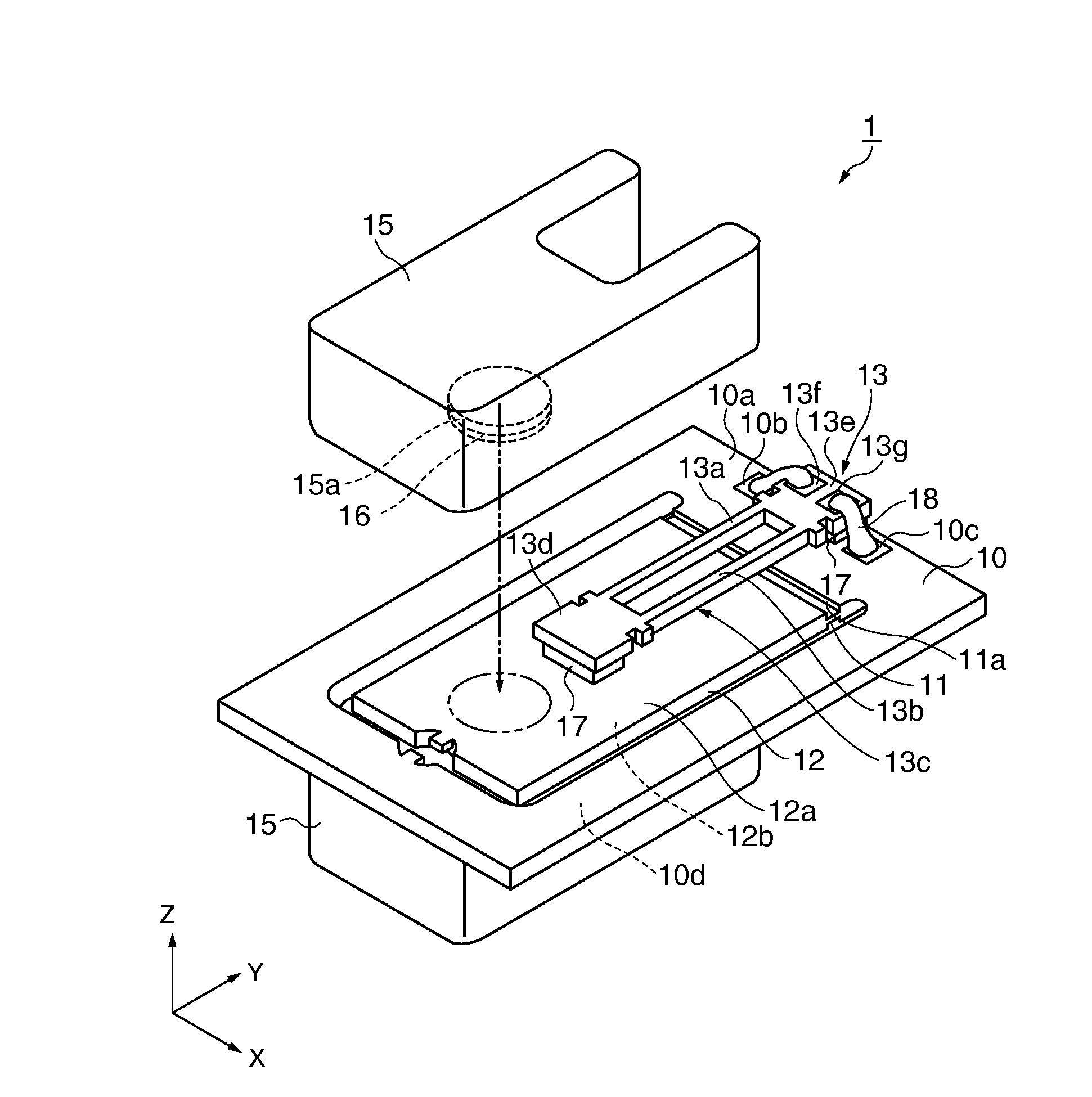
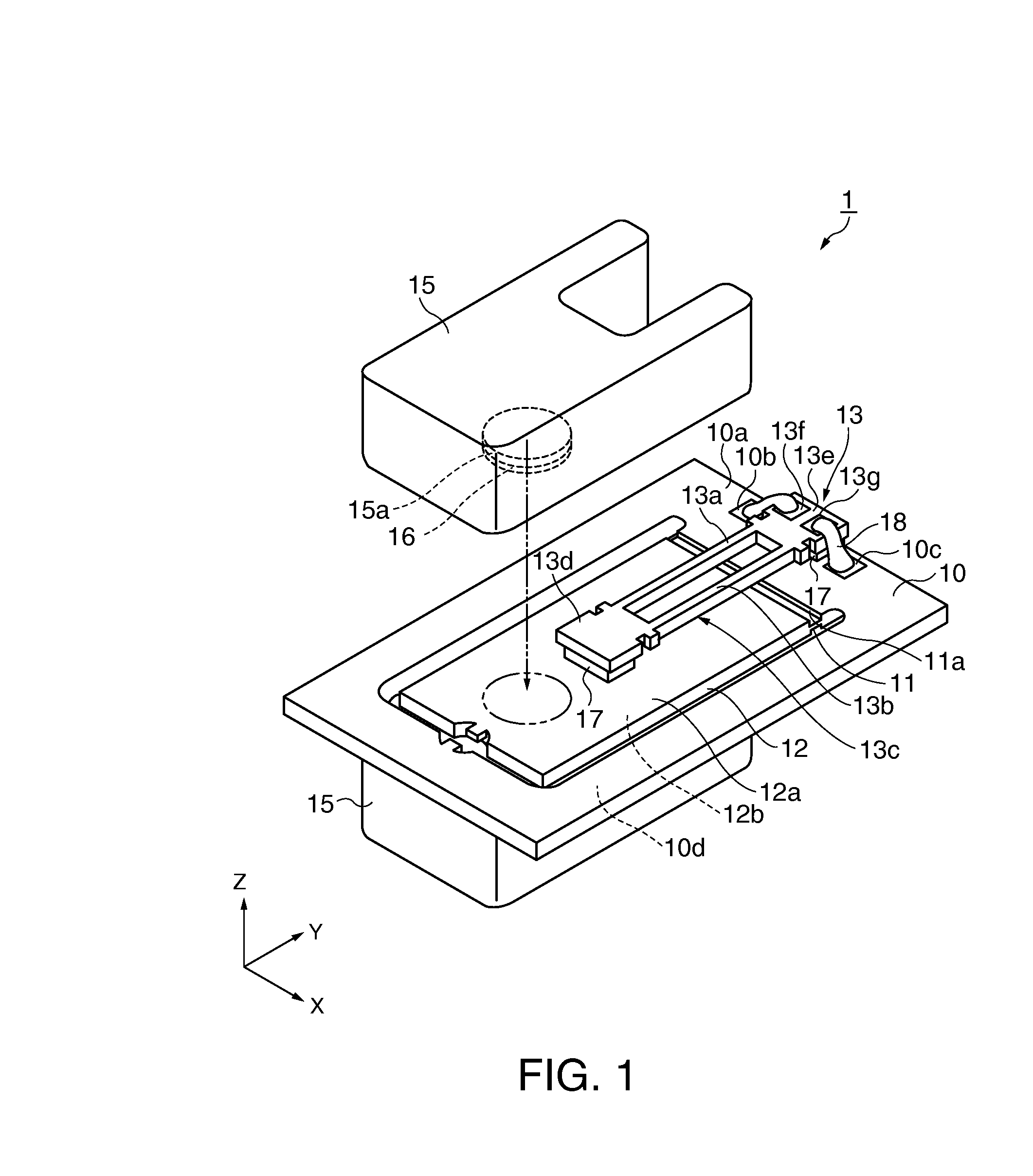
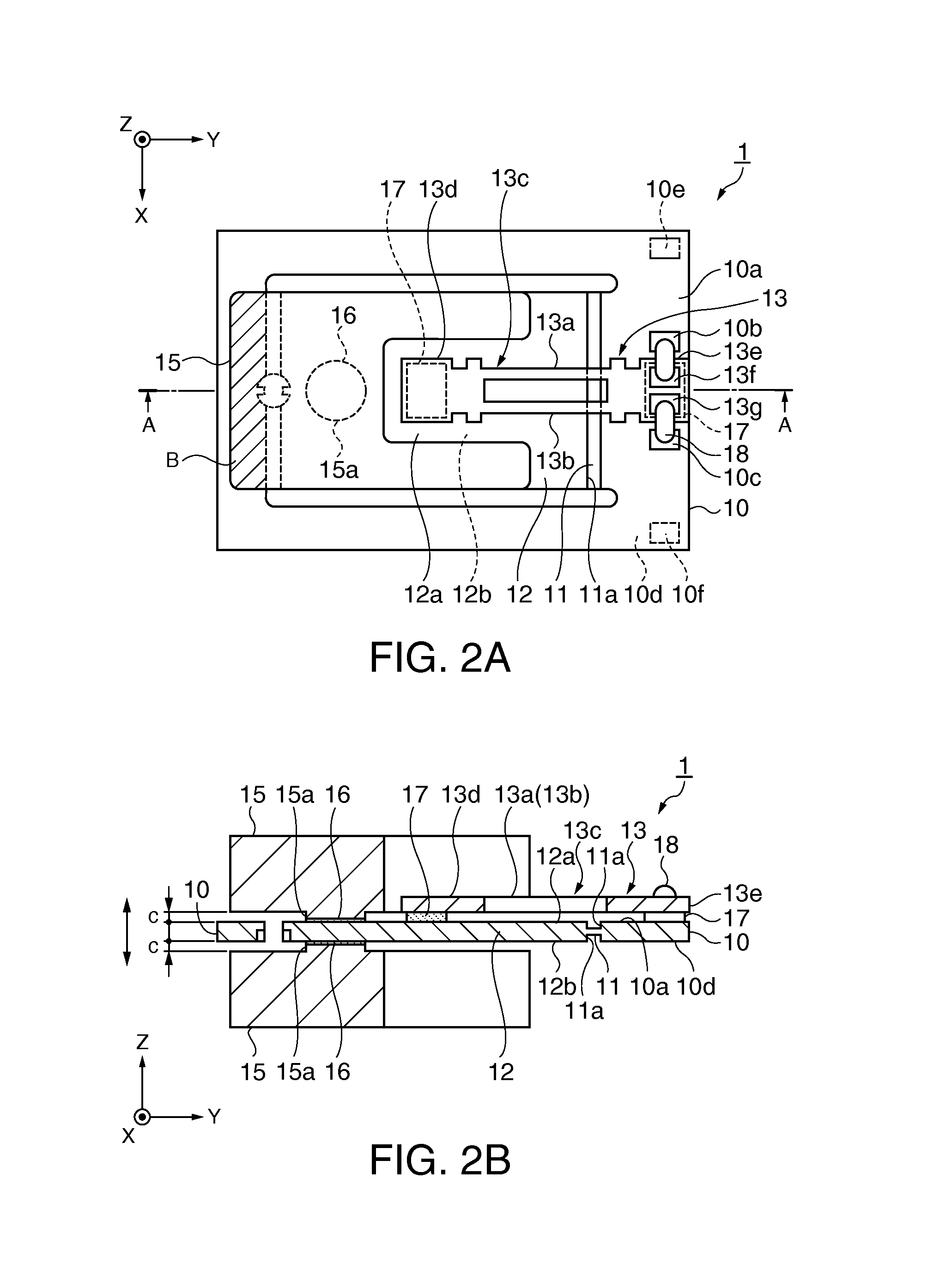
[0043]First, an example of the configuration of a physical quantity detector will be described.

[0044]FIG. 1 is a partly developed schematic perspective view showing a schematic configuration of an acceleration detector as an example of the physical quantity detector according to this embodiment. FIGS. 2A and 2B are schematic plan and sectional views showing a schematic configuration of the acceleration detector according to this embodiment. FIG. 2A is a plan view. FIG. 2B is a sectional view taken along line A-A in FIG. 2A. Wirings are omitted and dimensional proportions of individual components are different from reality.

[0045]As shown in FIG. 1 and FIGS. 2A and 2B, an acceleration detector 1 includes a flat frame-like base part 10, a rectangular flat plate-like moving part 12 which is arranged inside the frame of the base part 10 and has one end thereof (fixed end) connected to the base part 10 vie a joint part 11, and an acceleration detection element 13 as a physical quantity de...


PUM

PropertyMeasurementUnit
thicknessaaaaaaaaaa
thicknessaaaaaaaaaa
physical quantity detectoraaaaaaaaaa

Abstract

A method for manufacturing a physical quantity detector is for a physical quantity detector including a flat frame-like base part, a flat plate-like moving part which is arranged inside the base part and has one end thereof connected to the base part via a joint part, and a physical quantity detection element laid on the base part and the moving part. The method includes: integrally forming the base part, the joint part, the moving part, and a connecting part which is provided on a free end side of the moving part and connects the base part and the moving part to each other; laying and fixing the physical quantity detection element on the base part and the moving part; and cutting off the connecting part.

Description

BACKGROUND[0001]1. Technical Field[0002]The present invention relates to a method for manufacturing a physical quantity detector.[0003]2. Related Art[0004]Some acceleration detectors as physical quantity detectors are configured to utilize, for example, a phenomenon that the resonance frequency of a piezoelectric resonator element changes when a force in the direction of a detection axis acts on the piezoelectric resonator element, to detect acceleration applied to the acceleration detector based on this change in resonance frequency.[0005]For example, JP-A-8-54411 discloses an accelerometer (acceleration detector) which has a double-ended tuning fork-type piezoelectric resonator element bonded to one of opposite angles of a frame-shaped parallelogram frame and is configured to apply a compressive force or tensile force to the other of the opposite angles, and a manufacturing method for the same.[0006]The acceleration detector of JP-A-8-54411 includes a substantially flat plate-like...

Claims


Application Information

Patent Timeline
Patent Type & Authority Applications(United States)
IPC IPC(8): G01P15/00B23P17/04
CPCG01P15/0802G01P15/0922Y10T29/49817G01P2015/0828G01P15/097H05K3/4623Y10T29/49002Y10T29/49124Y10T29/49126
Inventor WATANABE, JUNNAKASENDO, KAZUYUKIKAMETA, TAKAHIRO
Owner SEIKO EPSON CORP
Why Eureka
Try Eureka