Injection molding method, injection-molded product, optical element, optical prism, ink tank, recording device, and injection mold

a technology of injection molding and injection molds, which is applied in the direction of envelope/bag making machinery, paper/cardboard containers, instruments, etc., can solve the problems of slow progress of solidification of the inside of the molten resin, difficulty in further suppressing sinking, and high surface accuracy, so as to achieve high quality, surface accuracy, and the effect of suppressing sinking

Inactive Publication Date: 2012-12-06
SEIKO EPSON CORP
View PDF10 Cites 6 Cited by
  • Summary
  • Abstract
  • Description
  • Claims
  • Application Information

AI Technical Summary

Benefits of technology

[0007]An advantage of some aspects of the invention is to suppress sinking that occurs in a high quality required surface more compared to sinking that occurs in a surface in which required surface accuracy is low, in an injection-molded product having the high quality required surface in which high surface accuracy is required and the surface in which required surface accuracy is lower than that of the high quality required surface.

Problems solved by technology

However, in the injection molding method disclosed in JP-A-2000-108185, since the entirety of the mold is opened or closed within a time when the molten resin injected and filled in a mold cavity is flowable, it is difficult to further suppress sinking, which occurs in the high quality required surface in which high surface accuracy is required compared to other surfaces.
Therefore, the progress of the solidification in the inside of the molten resin whose surface is solidified becomes slow at a portion that is close to the surface separated from the movable insert compared to portions that are close to surfaces that come into contact with a molding space forming section other than the movable insert.
As a result, a decrease in surface accuracy that is required for the high quality required surface may be suppressed, and therefore a decrease in the quality required for the injection-molded product may be suppressed.
Therefore, the progress of the solidification in the inside of the molten resin whose surface is solidified becomes slow at a portion that is close to the surface separated from the movable insert compared to portions that are close to surfaces that come into contact with a molding space forming section other than the movable insert.

Method used


Image

  • Injection molding method, injection-molded product, optical element, optical prism, ink tank, recording device, and injection mold
  • Injection molding method, injection-molded product, optical element, optical prism, ink tank, recording device, and injection mold
  • Injection molding method, injection-molded product, optical element, optical prism, ink tank, recording device, and injection mold

Examples


first embodiment

Configuration

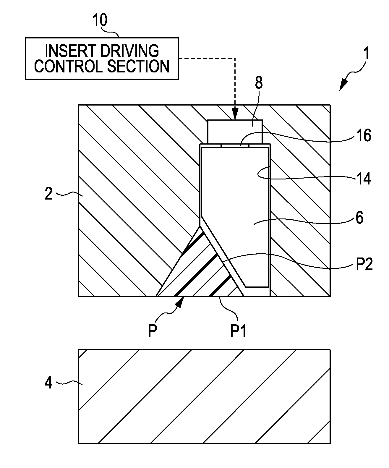
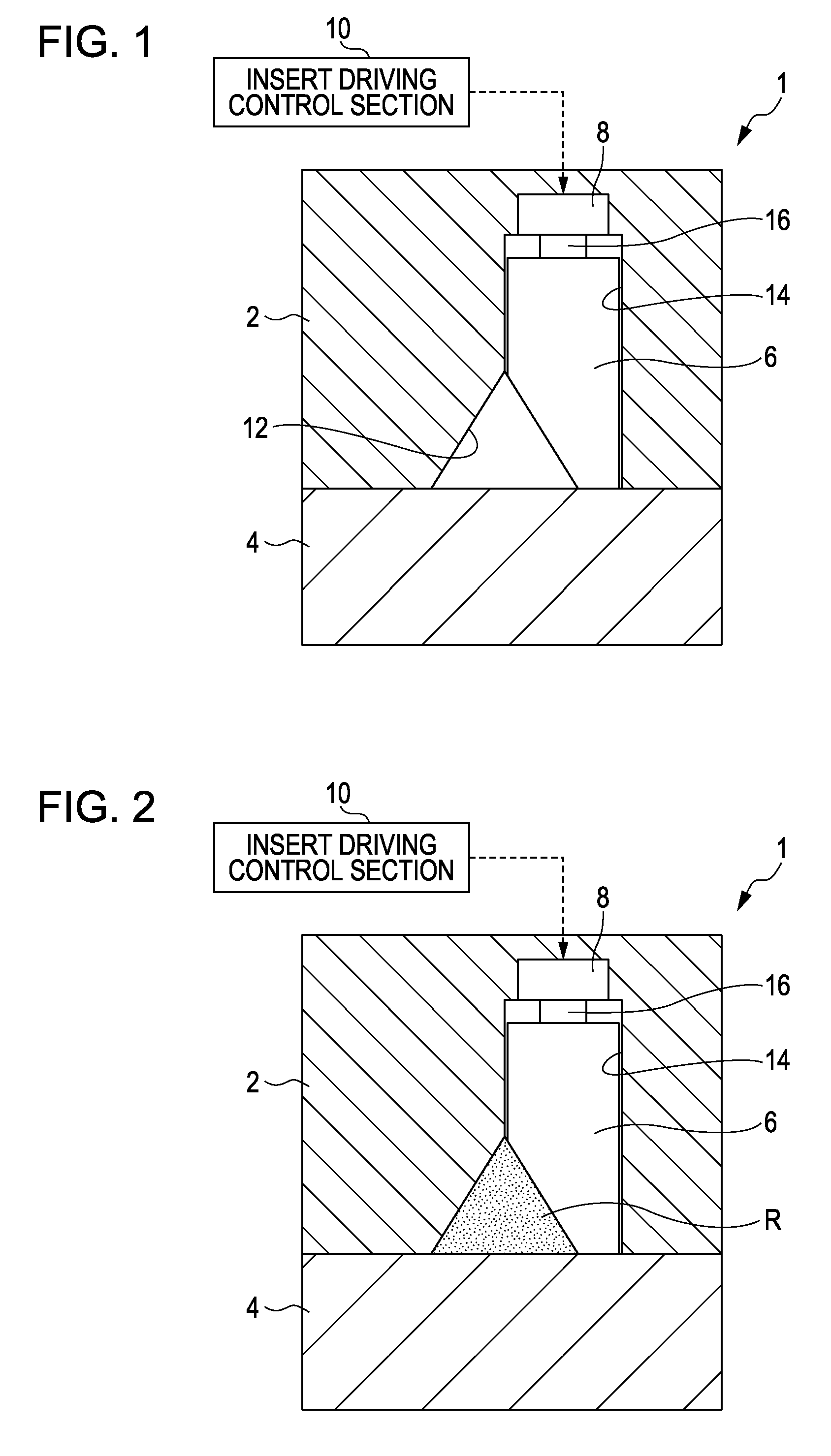
[0039]First, a configuration of the injection mold in the first embodiment will be described with reference to FIG. 1.

[0040]FIG. 1 shows a schematic configuration of the injection mold 1 and is a cross-sectional view of the injection mold 1.

[0041]The injection mold 1 shown in FIG. 1 is a device that injects a molten resin into a molding space (cavity), which is formed between a pair of molds in a case where the pair of molds in which mold opening and mold closing are possible is in a mold closed state, and solidifies the injected molten resin to manufacture an injection-molded product. In addition, a description with respect to the molding space will be made later.

[0042]Here, in the first embodiment, a description will be made with respect to a case in which the injection-molded product has light transmission properties and a cross-sectional shape thereof is a prism shape of an equilateral triangle or substantially equilateral triangle as an example. In this case, the i...

modification example

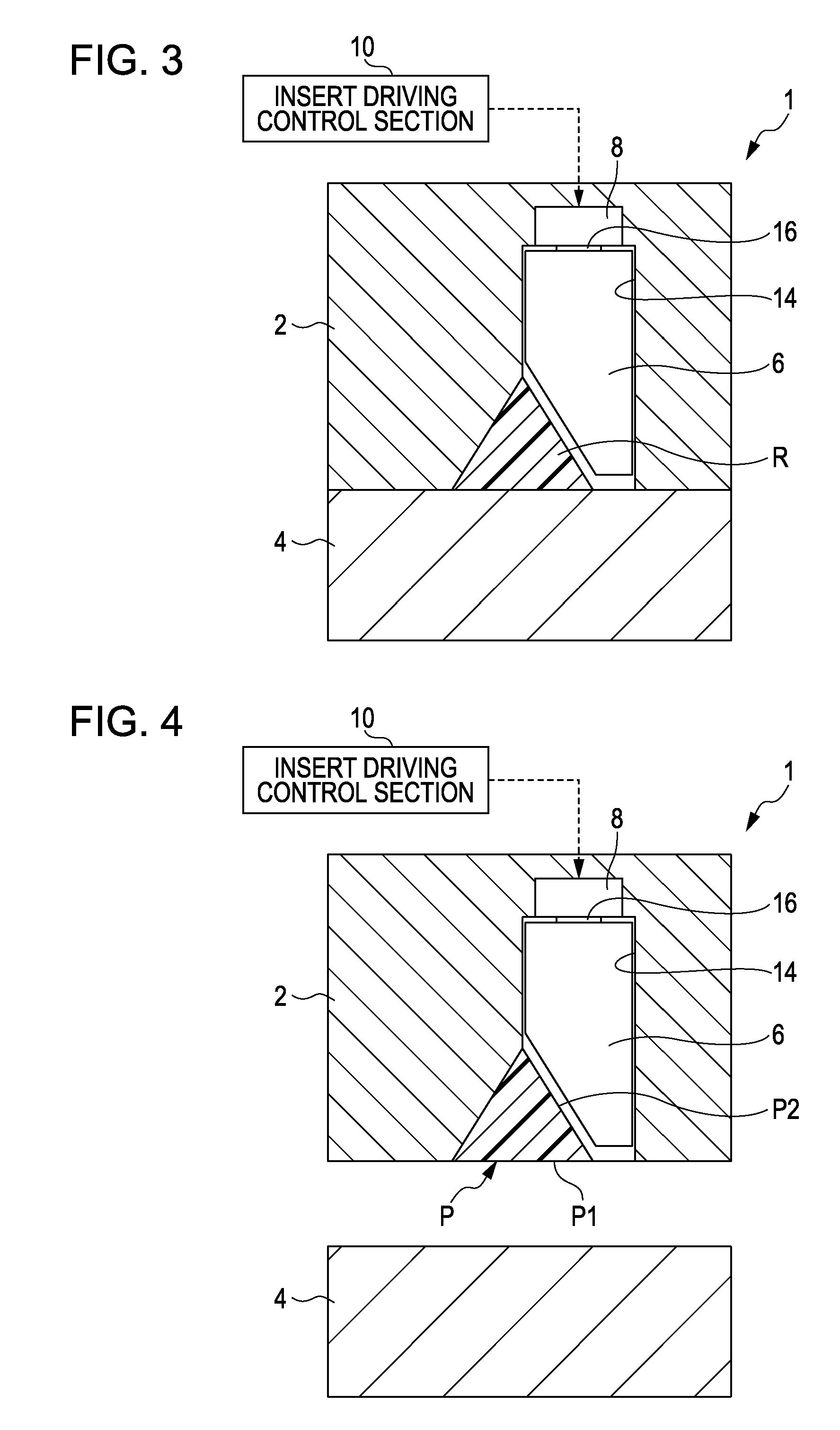
[0132]Hereinafter, a modification example of the first embodiment will be described.

[0133]In the first embodiment, the movable insert 6 is configured in such a manner that the surface (inclined surface), which is opposite to the fixed side opening portion 12, of the movable insert 6 is opposite to the entirety of the high quality not-required surface, but it is not limited thereto. That is, for example, as shown in FIG. 6, the movable insert 6 may be configured in such a manner that the surface, which is opposite to the fixed side opening portion 12, of the movable insert 6 is opposite to only a part of the high quality not-required surface. In addition, FIG. 6 is a view illustrating the modification example of the first embodiment.

[0134]In this case, for example, as shown in FIG. 6, the movable insert 6 is configured in such a manner that the surface, which is opposite to the fixed side opening portion 12, of the movable insert 6 is opposite to the center of the high quality not-re...


PUM

PropertyMeasurementUnit
shrinkage rateaaaaaaaaaa
surface accuracyaaaaaaaaaa
thicknessaaaaaaaaaa

Abstract

There is provided an injection molding method in which a molten resin, which is injected into a molding space formed between a fixed side mold including a movable insert and a movable side mold, is cooled in a state in which a surface of the molten resin comes into contact with the movable insert and thereby the surface is solidified, and internal solidification of the molten resin is completed by cooling the molten resin in a state where the molten resin and the movable insert are separated from each other by moving the movable insert before the internal solidification of the molten resin, whose surface is solidified in a state in which the surface comes into contact with the movable insert, is completed.

Description

BACKGROUND[0001]1. Technical Field[0002]The present invention relates to an injection-molded product, for example, an optical prism or the like that has a high quality required surface in which high surface accuracy is required, an injection mold and an injection molding method to manufacture the injection-molded product.[0003]2. Related Art[0004]In the related art, for example, as an injection molding method of manufacturing an injection-molded product such as an optical prism that has a high quality required surface in which high surface accuracy (flatness) is required, an injection molding method disclosed in JP-A-2000-108185 may be exemplified.[0005]In the injection molding method disclosed in JP-A-2000-108185, within a time when a molten resin injected and filled in a molding space is flowable, a molten resin is further injected while a mold is opened or after the mold is opened. Then, after entering a mold closed state, the mold is slightly opened to form a gap between a surfa...

Claims


Application Information

Patent Timeline
Patent Type & Authority Applications(United States)
IPC IPC(8): B29C45/72B32B1/02G02B5/04B32B3/30B29C45/33B41J2/175
CPCB29D11/00B29D11/0048B29C45/0025Y10T428/24479B29C45/26B29C45/7207Y10T428/13G02B5/04
Inventor YOKOTA, KEISHIOHARA, KEIICHI
Owner SEIKO EPSON CORP
Why Eureka
Try Eureka