Printing apparatus and method for paper cup

a printing apparatus and paper cup technology, applied in printing, typewriters, instruments, etc., can solve the problem of limiting the consumer's achieve the effect of promoting recycling of paper cups, improving sales effects, and convenient us

Inactive Publication Date: 2012-12-06
KIM MYEONG JU
View PDF4 Cites 19 Cited by
  • Summary
  • Abstract
  • Description
  • Claims
  • Application Information

AI Technical Summary

Benefits of technology

[0073]A paper cup printing apparatus according to the present invention includes a photographing unit that takes a photo, and a printing unit that prints the photo taken by the photographing unit on the surface of the paper cup and a method thereon automatically prints user's face or favorite images on the paper cup for containing coffee or drink, to thus encourage recycling of the paper cup.
[0074]In addition, the paper cup printing apparatus and method according to the present invention enables the pr

Problems solved by technology

However, because the conventional paper cup has a pre-printed premium indicating portion and a consumer may discard the paper cup after she or h

Method used


Image

  • Printing apparatus and method for paper cup
  • Printing apparatus and method for paper cup
  • Printing apparatus and method for paper cup

Examples


first embodiment

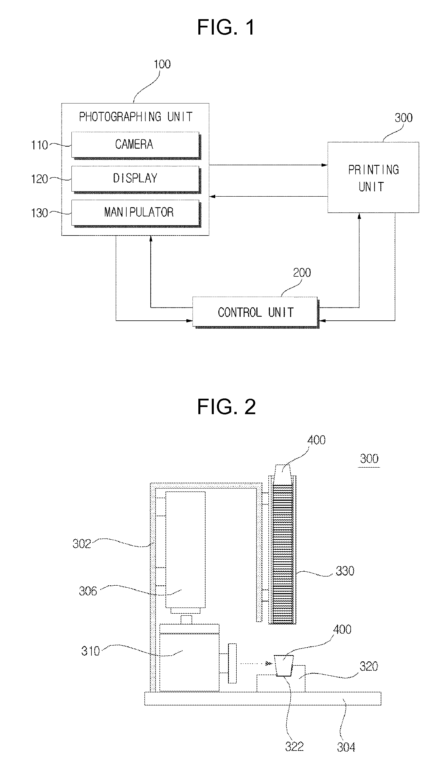
[0099]FIG. 2 is a side view showing a printing unit according to the present invention.

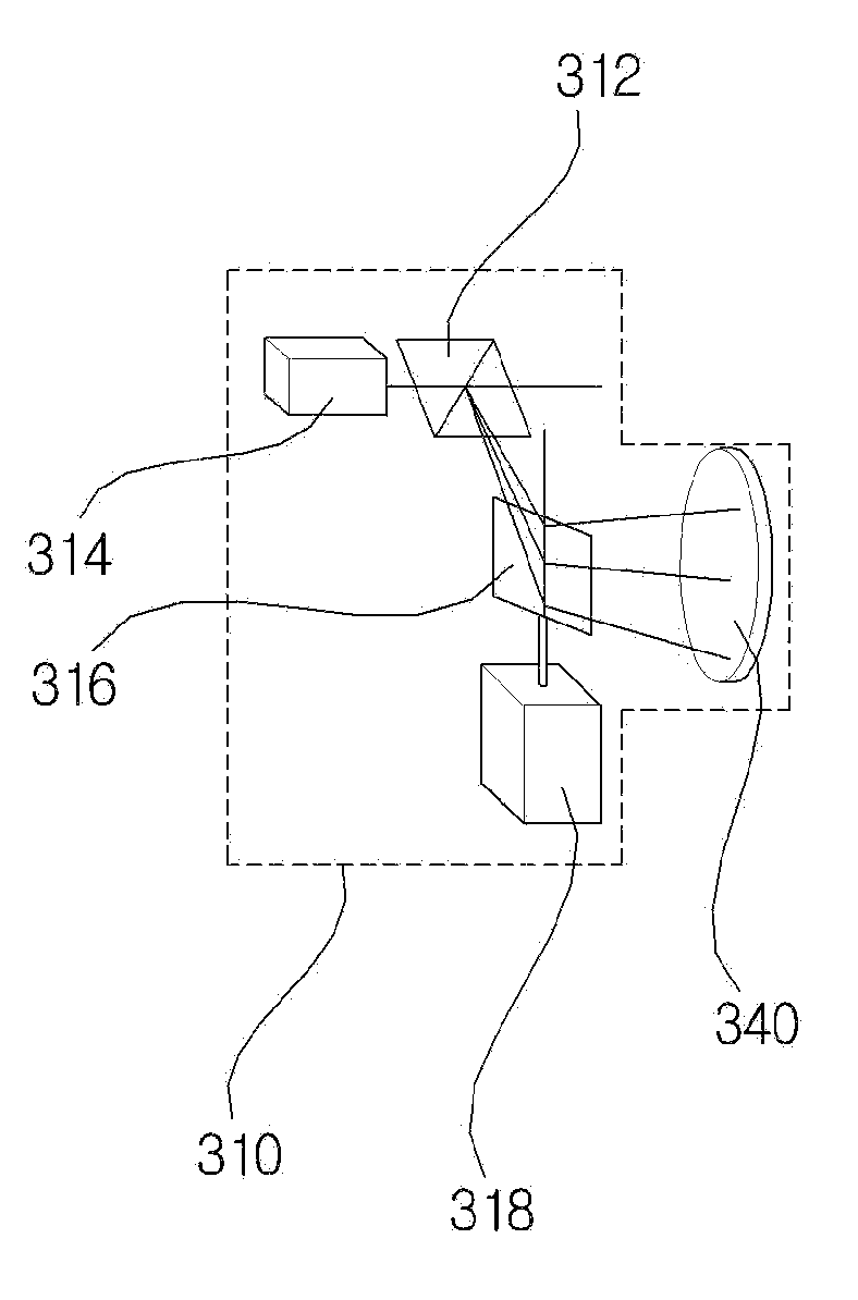
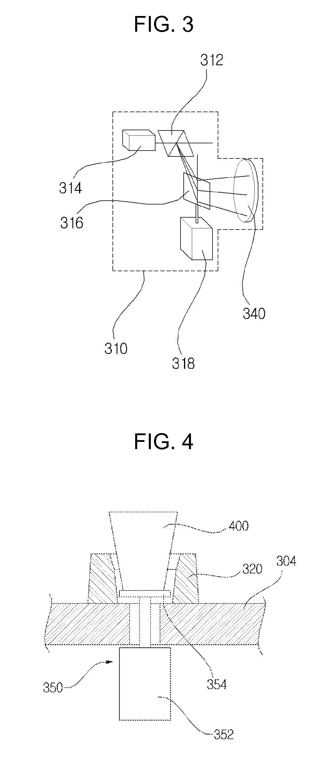
[0100]The printing unit 300 according to the first embodiment includes: a laser unit 306 that generates a laser beam; a scan head 310 that receives the laser beam generated in the laser unit 306, irradiates the received laser beam onto the surface of the laser beam of a paper cup 400, and controls a direction of the laser beam; and an alignment jig 320 that is placed in parallel with the scan head 310 to thus align the paper cup so that the scan head 310 faces the lateral surface of the paper cup 400.

[0101]The laser unit 306 is vertically erected in a housing 302, in which a laser beam irradiator that irradiates a laser beam is placed so as to face downward. Accordingly, the laser beam is irradiated vertically downwards. A table 304 is placed at the bottom of the housing 302, and the scan head 310 and the alignment jig 320 are installed on the table 304.

[0102]The laser unit 306 controls an intensi...

second embodiment

[0121]The printing unit 300 according to the present invention includes: a main body 10 that forms an external appearance;

[0122]a cup dispenser 20 that is placed in the inside of the main body 10 and that accommodates a plurality of paper cups; a cup withdrawal portion that withdraws one of the paper cups accommodated in the cup dispenser 20 to then be fixed on a cup holder 30; a cup alignment portion that rotates the cup holder 30 to align the paper cup 400 to match a printing position of the paper cup; a laser printer 40 that prints a photo or image on the surface of the paper cup 400; and a cup discharging portion that discharges the printing completed paper cup to the outside of the main body 10.

[0123]A paper cup exit 12 is provided on one lateral surface of the main body 10 in which the printing completed paper cup 400 is discharged through the exit 12. Although it is not shown in the drawings, a door is provided in the front surface of the upper side of the main body 10, in wh...


PUM


Abstract

Provided is a paper cup printing apparatus including: a photographing unit that takes a photo; a printing unit that prints the photo taken by the photographing unit on the surface of a paper cup; and a control unit that converts the photo taken by the photographing unit into data for printing, and controls the printing unit to automatically print the photo on the surface of the paper cup. The paper cup printing apparatus prints user's face or favorite image on a paper cup for containing coffee or drink to thus encourage recycling of the paper cup and increase sales of coffee or drink.

Description

CROSS-REFERENCE TO RELATED APPLICATION[0001]This application claims the benefit of Korean Patent Applications Nos. 10-2011-0077709, filed on Aug. 4, 2011, and 10-2011-0051252, filed on May 30, 2011, in the Korean Intellectual Property Office, the disclosure of which is incorporated herein by reference.BACKGROUND OF THE INVENTION[0002]1. Field of the Invention[0003]The present invention relates to a paper cup printing apparatus for printing a photo or image on a paper cup for containing coffee or drink and method thereof.[0004]2. Description of the Related Art[0005]Among the essential favorite foods of the moderns, there is a trend that coffee is increasingly consumed day by day. In particular, as take-out coffee shops are increasing, coffee put on disposable paper cups is being sold. In the Republic of Korea, the current annual consumption of paper cups is approximately estimated at 12 billion which corresponds to 1.2 million 20-year-old trees, and corresponds to the amount of reduc...

Claims


Application Information

Patent Timeline
IPC IPC(8): B41J2/435
CPCB41J3/44B41J3/4073B41F17/28B41F33/00
Inventor KIM, DONG GACK
Owner KIM MYEONG JU
Why Eureka
Try Eureka