
Method and apparatus for wirelessly synchronizing image shutter of image sensor and light source

Active Publication Date: 2012-12-06
STRYKER CORP
View PDF3 Cites 4 Cited by
  • Summary
  • Abstract
  • Description
  • Claims
  • Application Information

AI Technical Summary

Benefits of technology

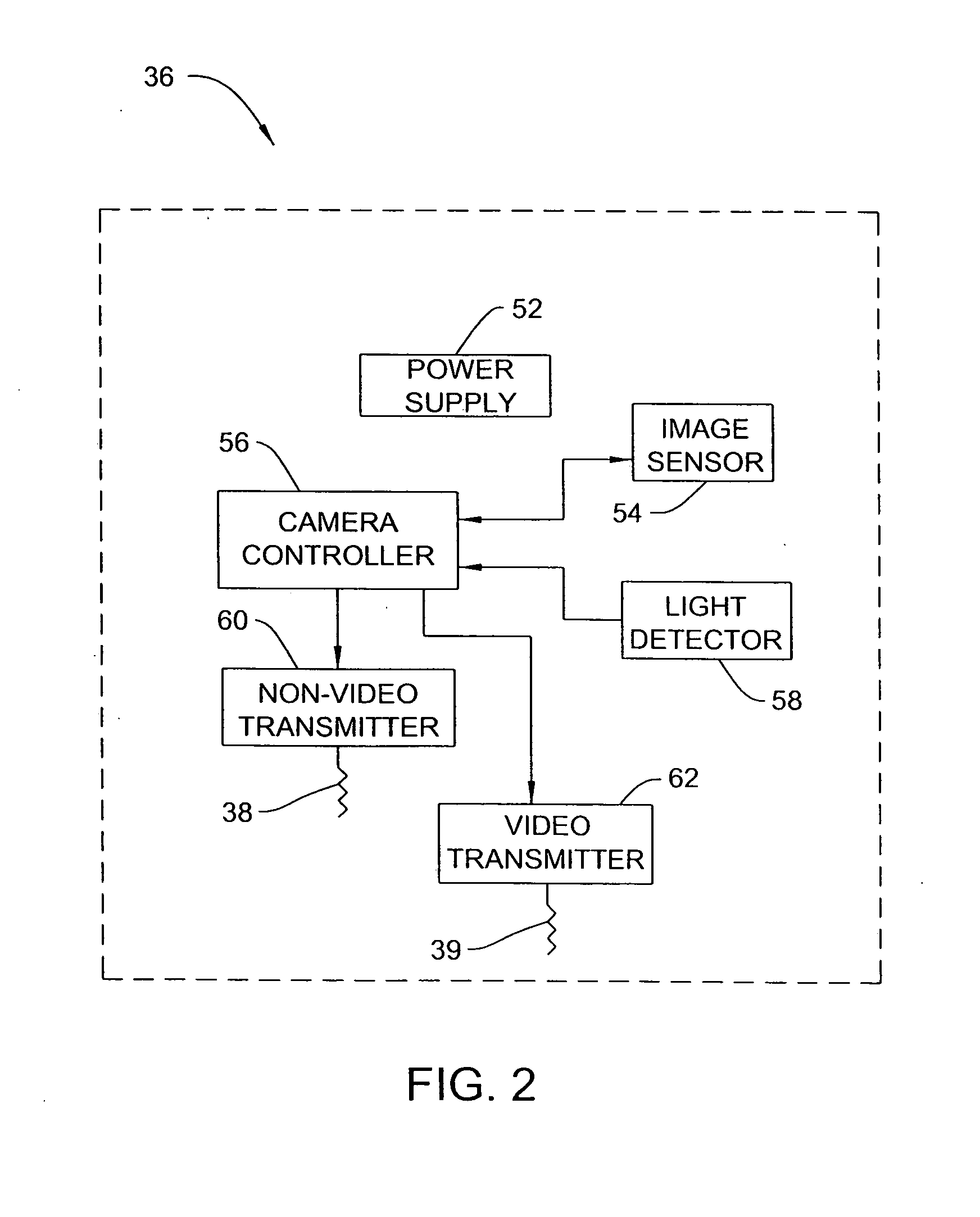
[0010]In another embodiment, the camera unit includes a photosensor or light detector separate from the image sensor for detecting the exact start time and time of operation that the light source provides light. The information determined by the light detector provides feedback to the camera controller for adjusting the information for the wireless control signals sent to the light source controller, to ensure that light source operation is synchronized with the electronic camera shutter of the video camera unit. The feedback provides a closed-loop system ensuring that operation of the light source is directly synchronized with the camera shutter of the video camera unit. The arrangement minimizes the usage of the battery for the light source unit, and thus reduces size and weight requirements for the battery.

Problems solved by technology

In such instances, providing a hard-wired connection between a camera controller and a light source controller is not practical as movement of the light source relative to the camera would be limited and awkward due to the presence of a connecting cable therebetween.
Further, a wired connection to a camera unit is not practical.
Constant output of light by the hand-held light source requires a large battery that results in a heavier light source unit to be manipulated and an undesirable output of heat and thus presents a technical problem.

Method used


Image

  • Method and apparatus for wirelessly synchronizing image shutter of image sensor and light source
  • Method and apparatus for wirelessly synchronizing image shutter of image sensor and light source
  • Method and apparatus for wirelessly synchronizing image shutter of image sensor and light source

Examples


Embodiment Construction

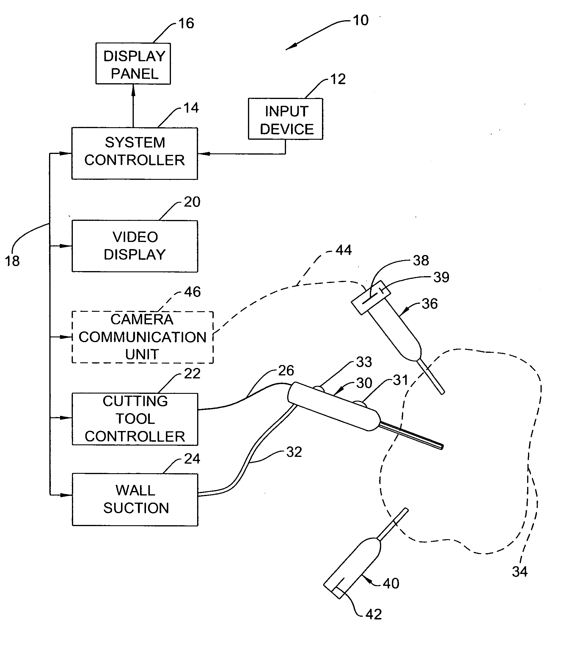
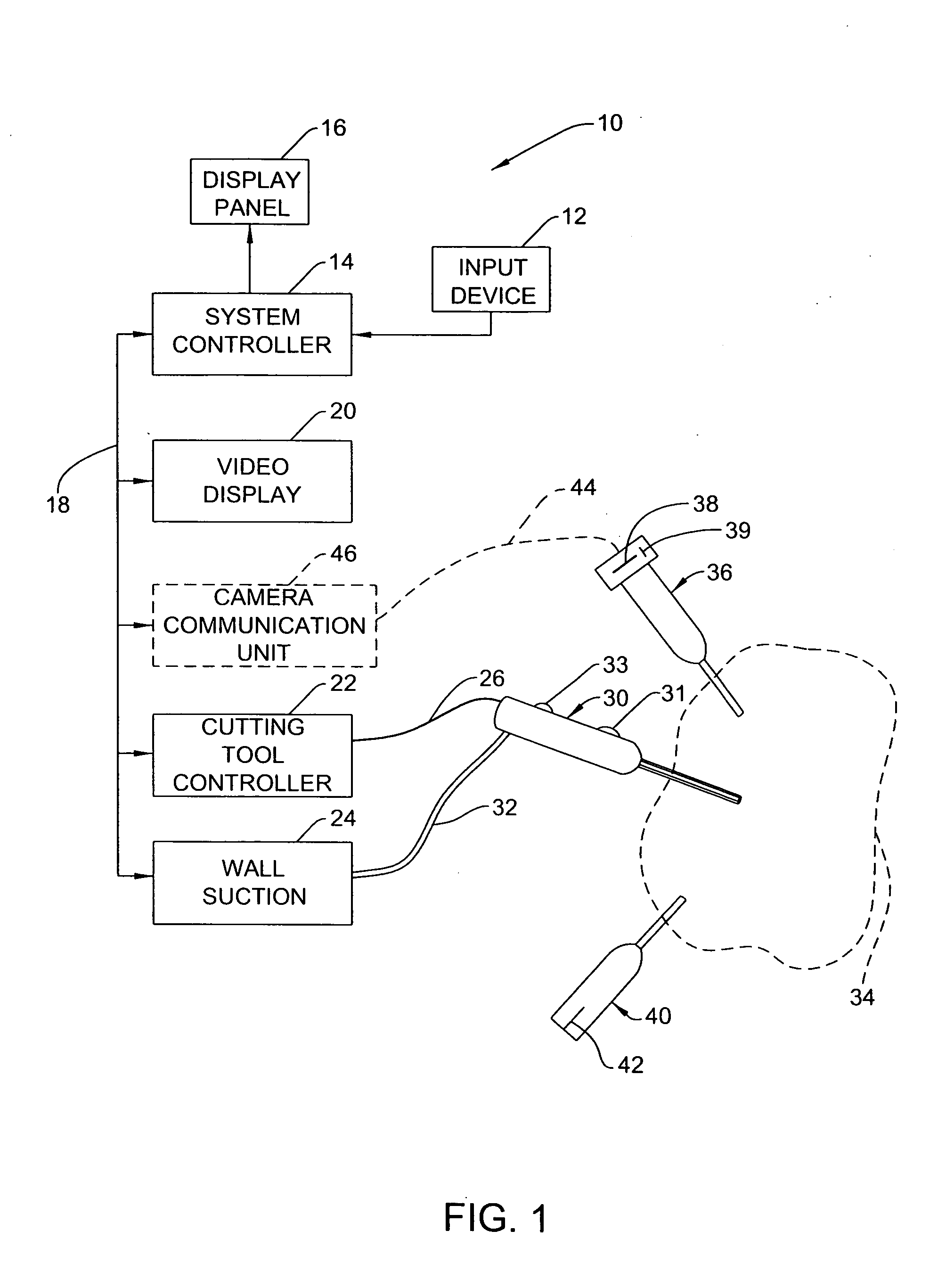
[0022]FIG. 1 shows an operating room control system 10 including an input device 12 for selectively providing input signals to a system controller 14. The system controller 14 is connected to a display panel 16. The system controller 14 is also connected via a network 18 to a plurality of surgical devices including a video display 20.

[0023]In FIG. 1, the system controller 14 is connected via the network 18 to a cutting tool controller 22 and a wall suction unit 24. A control signal line 26 connects the cutting tool controller 22 to an endoscopic cutting tool 30 having an on / off switch 31. Suction tubing 32 connected at one end to the wall suction unit 24 provides a suction flow path to the endoscopic cutting tool 30. The cutting tool 30 is a shaver or other cutting device and has a suction control activator 33 to remove tissue and debris from a surgical site 34.

[0024]FIG. 1 shows a wireless portable endoscopic video camera unit 36 having antenna arrangements 38, 39. The endoscopic w...


PUM


Abstract

A method and apparatus for wirelessly synchronizing operation of an image sensor of an endoscopic video camera unit having a wireless transmitter with operation of a portable endoscopic light source unit includes transmitting a message packet with a target camera shutter period, light source target phase / trigger time / OFF time and light source target ON time to the light source unit. The light source unit controls the start time and the ON time for light output by a light source. The video camera unit includes a light detector for detecting the actual light source start time and duration of light output to provide closed-loop feedback. A camera controller ensures synchronization between the shutter period of the image sensor and actual operation of the light source based on the actual phase and actual ON time sensed by the light detector and the previously communicated target phase / trigger time / OFF time and target ON time.

Description

FIELD OF THE INVENTION[0001]This invention is directed to a method and apparatus for wirelessly synchronizing operation of an endoscopic camera unit with operation of an endoscopic light source unit that is provided with a separate endoscopic device.BACKGROUND OF THE INVENTION[0002]The remote control of endoscopic devices connected to each other through hard-wired connections is well known for performing surgical procedures. A plurality of devices including cameras, cutting tools, irrigation devices, light sources, and suction devices are connected via a network to a system controller. The system controller is capable of communicating with and controlling the various devices.[0003]An endoscopic system with an irradiated light switching feature is disclosed in U.S. Pat. No. 7,258,663, issued Aug. 21, 2007. An endoscope of the system includes an image sensor incorporated in an insertion unit. The sensitivity of the image sensor can be varied by applying a plurality of pulsating drivin...

Claims


Application Information

Patent Timeline
IPC IPC(8): H04N5/04
CPCA61B1/00016A61B1/045G02B23/2484A61B1/0669H04N5/2354H04N7/185H04N2005/2255H04N5/2353A61B1/0655H04N23/555H04N23/73H04N23/74A61B1/00006A61B1/00057A61B1/044A61B1/0661
Inventor NAMBAKAM, VASUDEV
Owner STRYKER CORP
Learn More