
Miniature multilayer radiative cooling case wtih hidden quick release snaps

a cooling case and multi-layer technology, applied in the direction of closed casings, electrical apparatus construction details, instruments, etc., can solve the problems of increasing the chance of liquid and insect entry into the cooling case, damage to the cooling box,

Active Publication Date: 2012-12-06
INTERDIGITAL CE PATENT HLDG
View PDF15 Cites 16 Cited by
  • Summary
  • Abstract
  • Description
  • Claims
  • Application Information

AI Technical Summary

Problems solved by technology

Particular problems that set-top boxes face are damage due to liquid entry, insect entry, and heat generation.
However, venting apertures, which are often used for heat dissipation, unfortunately increase the opportunity of liquid and insect entry.

Method used


Image

  • Miniature multilayer radiative cooling case wtih hidden quick release snaps
  • Miniature multilayer radiative cooling case wtih hidden quick release snaps
  • Miniature multilayer radiative cooling case wtih hidden quick release snaps

Examples


Embodiment Construction

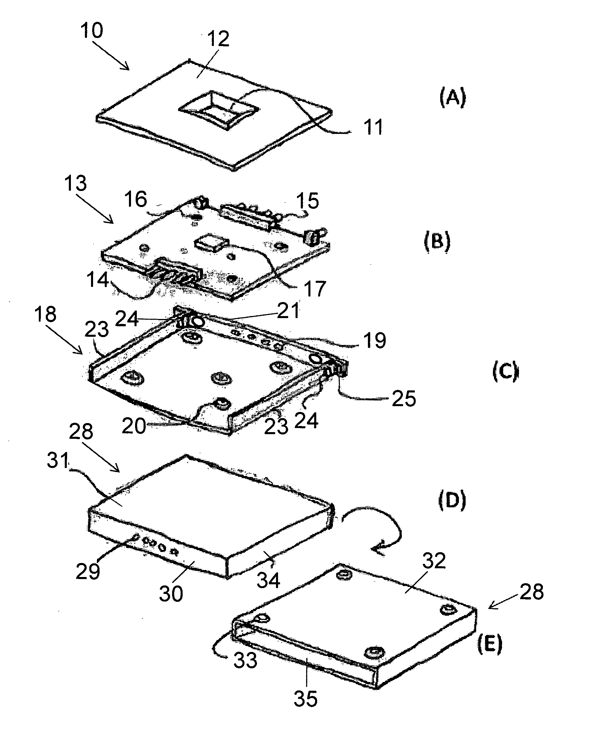
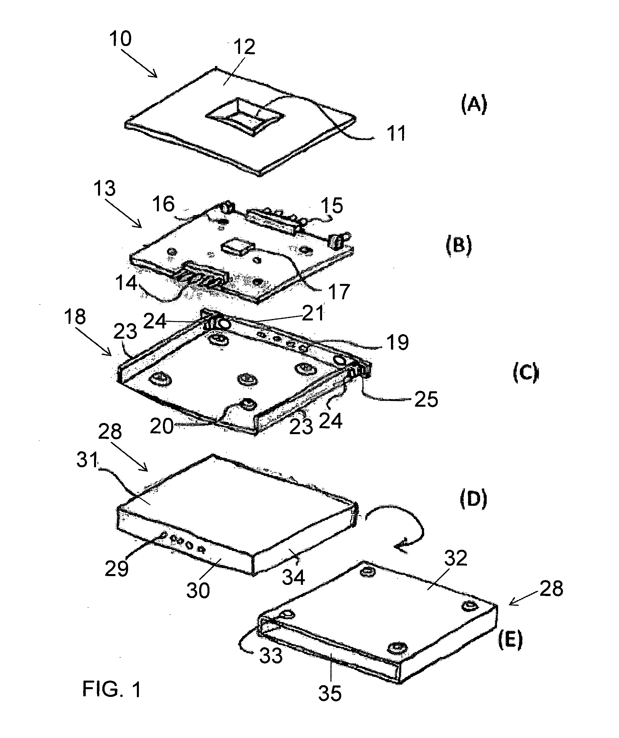
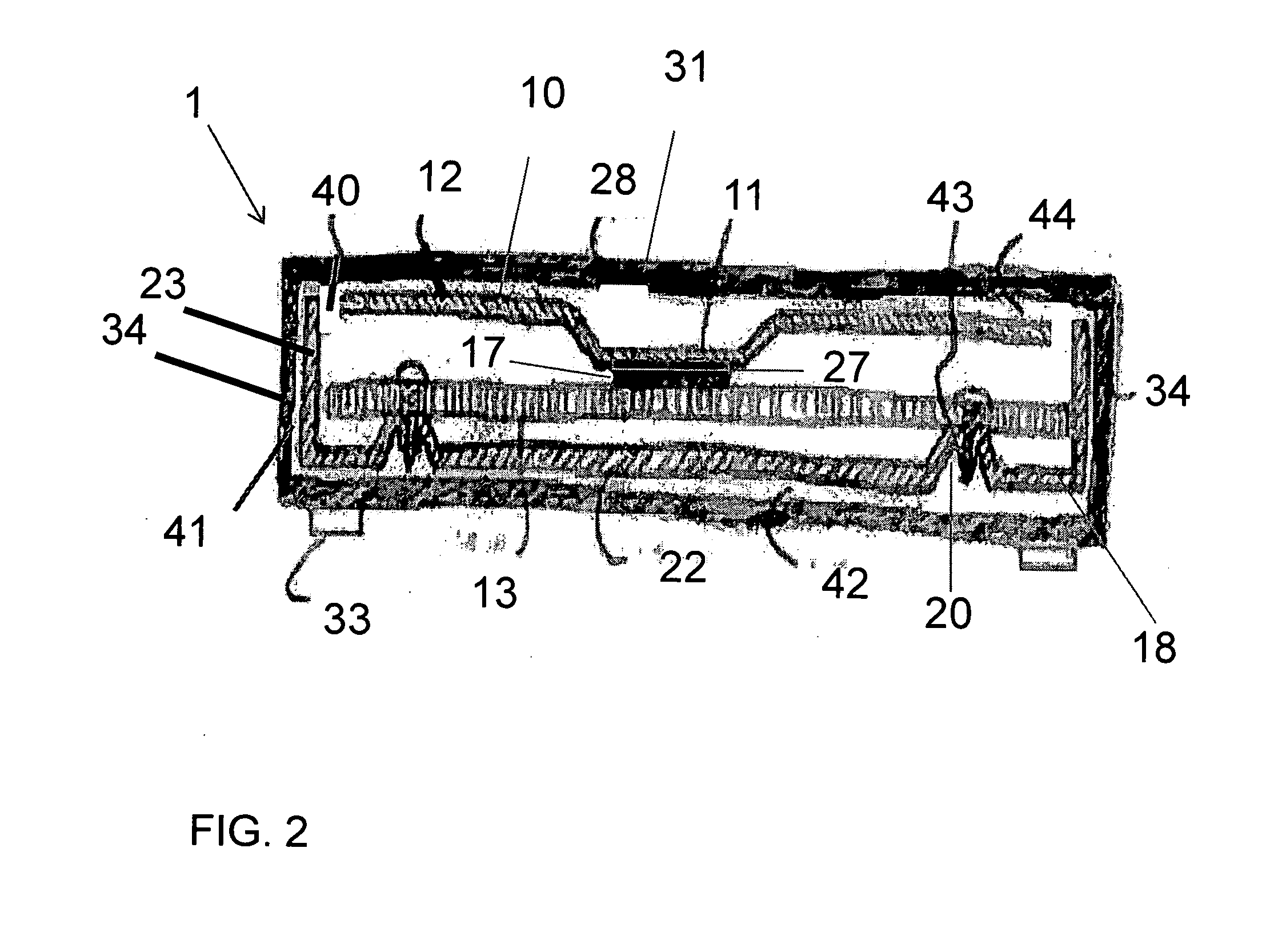
[0020]The set-top box 1 or the like according to the invention includes the various components which are shown in FIG. 1 and includes a top broad heat sink 10, a main printed circuit board 13, a frame pan 18, and an outer cover 28.

[0021]More particularly, FIG. 1A shows a top broad heat sink 10, which is an internal component. The top broad heat sink 10 can be a generally contoured plate that has a generally planar periphery 12 and a contoured central feature such as a pocket, central depression, notch, recess, multilevel depression, mesa extending from and / or into a plane of the planar periphery. The central feature or central depression 11 can have side walls extending from the planar periphery and form an obtuse angle therewith. The contoured feature can have a flat bottom designed to contact the main integrated circuit and / or other heat generating component 17.

[0022]FIG. 1B shows a main printed circuit board 13 or the like, which can be generally flat. The main printed circuit bo...


PUM


Abstract

A passive cooling arrangement for an electronic housing assembly is disclosed which comprises a frame disposed in the housing assembly; a circuit board supported in the frame; a heat generating component disposed on the circuit board; and a heat sink configured with a substantially flat peripheral portion and a depression portion, the substantially flat peripheral portion facing and being nearly coextensive with an outer wall of said housing assembly, and the depression portion being in thermal engagement with the heat generating component on the circuit board, whereby heat generated by the heat generating component can be passively thermally conducted through the depression portion and into the substantially flat peripheral portion of the heat sink, and thereafter dissipated in a generally uniform manner through the outer wall of the housing assembly. The frame comprises a base with embosses which support the circuit board in a position enabling the thermal engagement of the heat generating component and the depression portion of the heat sink. The outer wall of the housing assembly is preferably unvented and the housing assembly is preferably oriented in use with the outer wall facing upwardly.

Description

CROSS-REFERENCE TO RELATED APPLICATIONS[0001]This application claims priority from U.S. Provisional Application Ser. No. 61 / 338,907 filed Feb. 25, 2010, which is incorporated by reference herein in its entirety.FIELD OF THE INVENTION [0002]The present invention relates to quiet set-top boxes having improved heat dissipating capabilities.BACKGROUND OF THE INVENTION[0003]Set-top boxes continue to be in high demand and an ever increasing need exists to reduce the size and improve aesthetic appeal, performance, and robustness of these devices and the like.[0004]Particular problems that set-top boxes face are damage due to liquid entry, insect entry, and heat generation. However, venting apertures, which are often used for heat dissipation, unfortunately increase the opportunity of liquid and insect entry. As such, a need exists to address each of these problems without creating or augmenting other problems.[0005]An additional consideration in designing set-top boxes to keep in mind is t...

Claims


Application Information

Patent Timeline
Patent Type & Authority Applications(United States)
IPC IPC(8): H05K7/20
CPCH05K7/20445H01L2924/0002H01L2924/00H01L23/4006H05K5/0008H05K7/20163G06F1/1656H05K7/20436H05K13/00
Inventor RITTER, DARIN BRADLEYHUNT, MICKEY JAYGYSIN, MARK WILLIAM
Owner INTERDIGITAL CE PATENT HLDG
Learn More