Supercharge Your Innovation With Domain-Expert AI Agents!

Turbine nozzle slashface cooling holes

a technology of turbine nozzles and cooling holes, which is applied in the direction of machines/engines, stators, mechanical equipment, etc., can solve the problems of irreparable damage to the nozzle or the vane segment, degrade and the temperature on the sidewall of the vane segment can be significant, so as to achieve the effect of not degrading the performance of the turbine engine and being less expensiv

Active Publication Date: 2012-12-06
GENERAL ELECTRIC CO
View PDF5 Cites 0 Cited by
  • Summary
  • Abstract
  • Description
  • Claims
  • Application Information

AI Technical Summary

Benefits of technology

The present invention relates to a solution for preventing damage to turbine components in high-temperature gas turbine engines caused by the high temperature of the combustion gases. The invention addresses the issue of hot gas damaging the vane and blade segments in the turbine stator assembly and the nozzle diaphragm. The invention provides a cooling solution for the intersegment gap between the inner bands of the vane segments and the outer bands of the blade segments, which can help prevent damage to the engine. The cooling solution involves the use of cooling passages formed in the inner band and exiting through the outer band, which can be done without compromising the performance of the turbine engine.

Problems solved by technology

It has been determined that there is the potential for significant increases in temperature on the sidewalls of the vane segments, due to a lack of cooling air sweeping over the intersegment gap between two adjacent vane segments.
The most problematic is the vane segment side edge, or slashface, closest to the leading edge of one of the vane segment airfoils, where combustion gas pressure is highest.
The concentrated heat load can potentially result in oxidation, cracking and burning, often resulting in irreparable damage to the nozzle or vane segment.
This option, however, significantly degrades performance of the turbine engine due to the diversion of relatively large amounts of compressor discharge air to pressurize the nozzle diaphragm.

Method used


Image

  • Turbine nozzle slashface cooling holes
  • Turbine nozzle slashface cooling holes
  • Turbine nozzle slashface cooling holes

Examples


Embodiment Construction

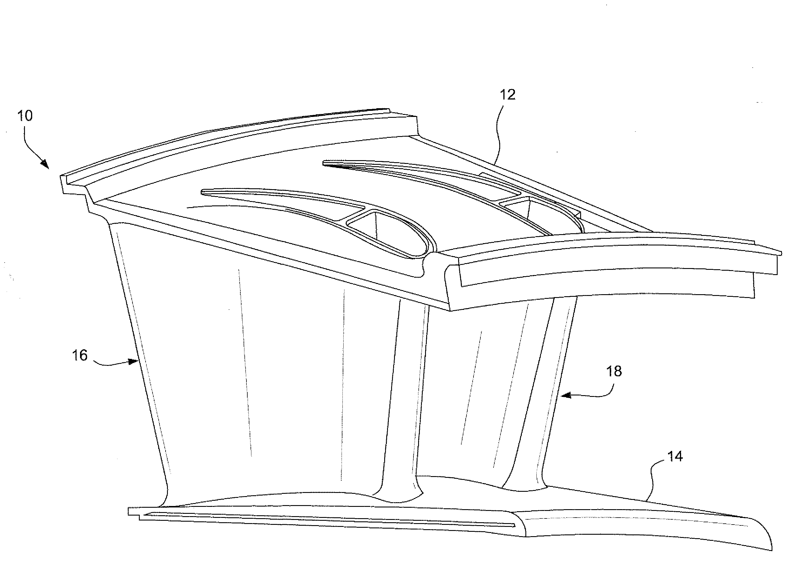
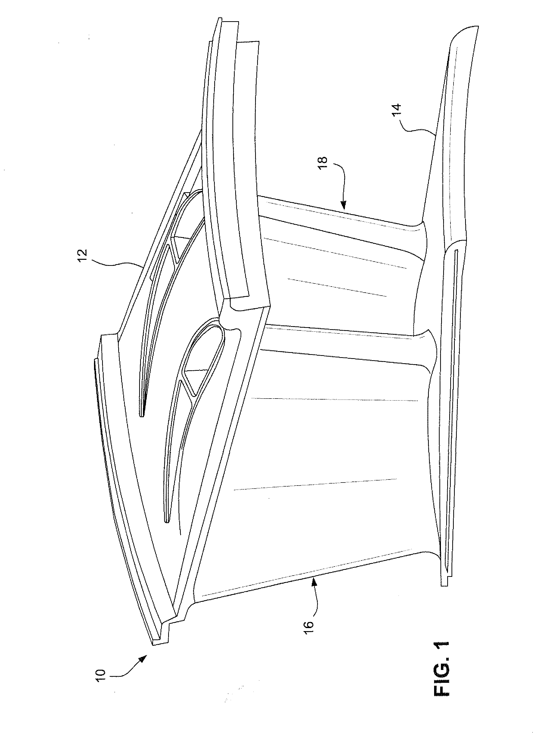
[0015]With reference especially to FIGS. 1-4, a turbine vane segment 10 includes a radially outer band or shroud 12 and a radially inner band or shroud 14. Between the inner and outer bands, there is a pair of airfoils 16 and 18 (a two-airfoil segment is sometimes referred to as a “doublet”). Other vane segments may have one or more than two individual airfoils, and the invention here is not limited to any particular number of airfoils in the vane segment. The airfoils 16 and 18 are substantially identical with the exception of their orientation relative to the inner and outer bands. Accordingly, and with reference especially to FIG. 3, it may be seen that the blade or airfoil 16 has a leading edge 20, a trailing edge 22, a pressure side 24 and a suction side 26.

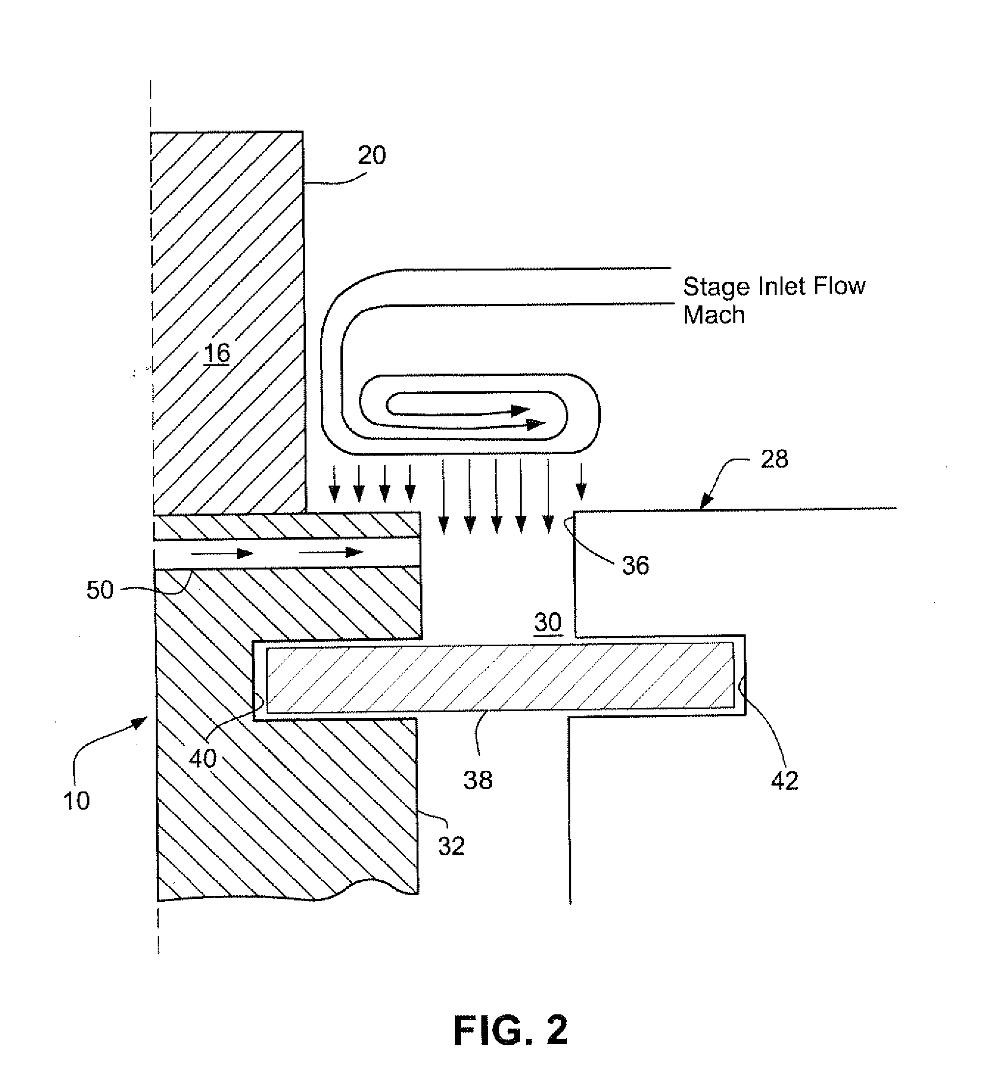
[0016]The individual arcuate vane segments 10 are arranged in a stationary, annular array about the turbine rotor as is well understood in the art. FIGS. 2 and 3 show a pair of vane segments 10 and 28 as they would appear in...


PUM


Abstract

A turbine vane or blade segment includes at least one airfoil extending radially outwardly from a radially inner band. The radially inner band is formed with substantially axially-extending side edges, and the at least one airfoil is formed with a leading edge, a trailing edge, a pressure side, a suction side, and an internal cooling plenum. The pressure side faces one of the substantially axially-extending side edges and the leading edge is located proximate to that one edge. A plurality of cooling passages are formed in the radially inner band in fluid communication with the internal plenum and exiting the inner band via a plurality of exit holes in the one of the substantially axially-extending side edges. The plurality of exit holes are confined to a region along the one of the substantially axially-extending side edges where static pressure PS along the one of the substantially axially-extending side edges lies in a pressure range, ΔPD, substantially between the stage inlet total pressures PT that is substantially about 1.5 times the dynamic pressure range ΔPD, below the stage inlet total pressure.

Description

BACKGROUND AND SUMMARY OF THE INVENTION[0001]The present invention relates generally to turbomachines and more particularly to vane and blade assemblies utilized in the high pressure turbine section of gas turbine engines.[0002]It is desirable to operate a gas turbine engine at high temperatures most efficient for generating and extracting energy from the combustion gases. Certain components of the gas turbine engine, for example, stationary vane segments of a turbine stator assembly which closely surround the turbine rotor and which define the outer boundary for the hot combustion gases flowing through the turbine, are directly exposed to the heated stream of combustion gases. The vane segments typically incorporate one, two or more individual vanes or airfoils extending between inner and outer bands or shrouds.[0003]It has been determined that there is the potential for significant increases in temperature on the sidewalls of the vane segments, due to a lack of cooling air sweepin...

Claims


Application Information

Patent Timeline
Patent Type & Authority Applications(United States)
IPC IPC(8): F01D25/12
CPCF05D2270/3015F01D5/187F01D9/065F01D11/006F05D2240/81Y02T50/60
Inventor SEWALL, EVAN ANDREWVEHR, JAMES WILLIAMROBERTS, JR., FREDERIC WOODROW
Owner GENERAL ELECTRIC CO
Features
  • R&D
  • Intellectual Property
  • Life Sciences
  • Materials
  • Tech Scout
  • Unparalleled Data Quality
  • Higher Quality Content
  • 60% Fewer Hallucinations
Learn More