In-Situ Detection and Analysis of Methane in Coal Bed Methane Formations with Spectrometers
Active Publication Date: 2012-12-13
GAS SENSING TECH CORP
View PDF8 Cites 51 Cited by
Summary
Abstract
Description
Claims
Application Information
AI Technical Summary
This helps you quickly interpret patents by identifying the three key elements:
Problems solved by technology
Method used
Benefits of technology
Benefits of technology
[0057]By combining zonal isolation and downhole spectroscopic fluid analysis in a specific manner, this invention provides the unexpected benefit of enabling in-situ measurement of fluid properties for multiple zones in a single wellbore without requiring an intervening cemented casing, allowing fast, accurate evaluation of multiple possible production zones in a single well. The method further allows differentiation of fluids from each of these zones, and thereby differentiation of the properties of the formations. The method allows the possibility of determination of cross communication between formations at locations away from the wellbore.
[0058]A further unexpected benefit involves the resulting ability to move fluids into a
Problems solved by technology
The primary issue developing a method in identifying such coal seams involves developing a method and apparatus to quickly and accurately analyze coal seams for gas content.
However, collection of the coal sample usually changes its gas content to a significant extent before gas desorption is monitored.
This degradation of sample integrity leads to degradation of the data collected.
That degradation of data creates significant doubt in the results of those common methods.
As well, because these methods hinge on waiting for the methane to desorb from the coal, they require inordinate amounts of time and expense before the data is available.
A coal bed methane well with coal to methane and, possibly, bacterial material, provides an environment too complex for such a device to differentiate methane and the other substances of interest.
The device is not capable of resolving signals from different hydrocarbons to a useful extent, and the device is not capable of accurate measurements needed for coal bed methane wells.
Furthermore, the requirements that the sample be fluid, that analysis occur via optical transmission through the sample, and that the sample be examined internal to the device precludes its use for applications such as accurately measuring gas content of coal seams.
roscopy. However, the stated requirement that the Raman spectrometer be remote from the sam
Method used
Image
Click on the blue label to locate the original text in one second.
Reading with bidirectional positioning of images and text.
Examples
Example
[0094]The accompanying drawings, which are incorporated in and constitute a part of the specification, illustrate preferred embodiments of the invention. These drawings, together with the general description of the invention given above and the detailed description of the preferred embodiments given below, serve to explain the principles of the invention.
DETAILED DESCRIPTION OF THE DRAWINGS
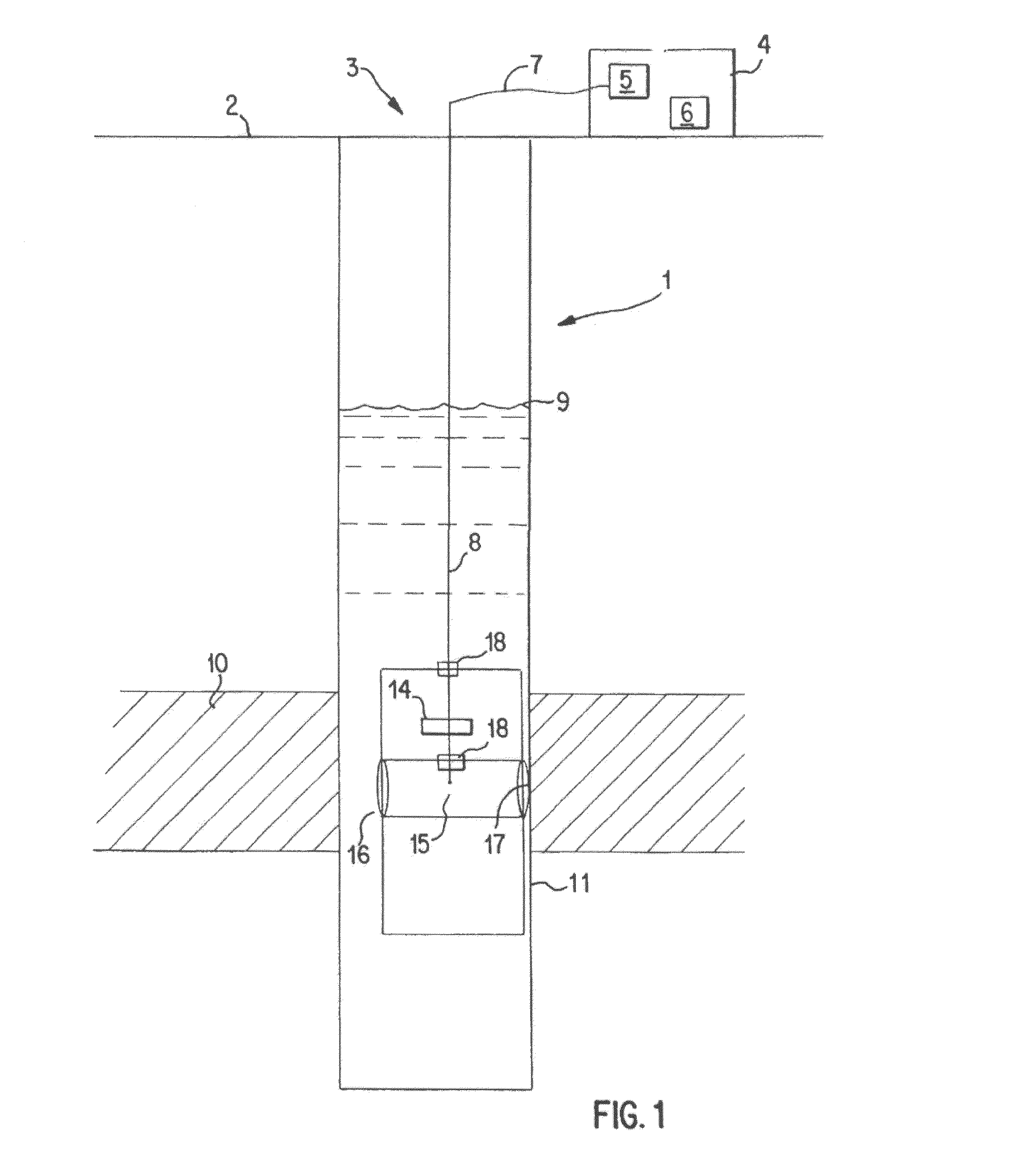
[0095]FIG. 1 shows a coal bed methane well 1 with a borehole 3 extending from a well head to a coal seam 10 with an aquifer fed water level 9. The spectrometer4 is located at or near the wellhead and includes a radiation source 5 for producing a radiation to transmit down the borehole 3 to a sample interface 17. The radiation from the radiation source is transmitted by way of at least one optical pathway 7. The sample, in this case beings water, interacts with the radiation transmitted from the radiation source 5, and a characteristic radiation for the sample is produced by the interaction. The ch...
PUM
Abstract
Disclosed is a system for measuring a chemical in a subsurface formation comprising housing component traversable within the well, a guide extending down the well from a fixed location being operatively connected to the housing, a radiation source, and an optical pathway between a sample and detector wherein the detector is located at the ground surface. Also disclosed is a method for reducing long distance transmission of radiation comprising placing a radiation source in a housing, placing a housing down in a well bore, lowering a spectrometer down the well bore, and controlling movement of a spectrometer by a guide wire controller at the ground surface. Further disclosed is a method of radiating a sample comprising, transmitting the radiation through at least one optical pathway, interacting a sample with the radiation, producing characteristic radiation from the sample, and transmitting by an optical pathway to a detector located in a spectrometer.
Description
CROSS REFERENCE TO RELATED APPLICATIONS[0001]This application is a continuation in part reissue application Ser. No. 11 / 332,388 filed Jan. 13, 2006 of U.S. Pat. No. 6,678,050 which claims priority to International Patent Application No. PCT / US01 / 11563, filed Apr. 11, 2001, designating the United States of America, and published as WO 01 / 77628, the entire disclosure of which is incorporated herein by reference. U.S. Pat. No. 6,678,050 claims priority based on Provisional Application Nos. 60 / 196,620, 60 / 196,182, 60 / 196,523 and 60 / 196,000 filed Apr. 11, 2000. This application is also a continuation in part of application Ser. No. 11 / 855,945 filed Sep. 14, 2007 and claiming priority to U.S. Provisional Patent Application No. 60 / 661,152. The entire disclosure of which is hereby incorporated by reference. This application also is a continuation in part of provisional application No. 61 / 602,939 filed Feb. 24, 2012 entitled “In-situ Detection and Analysis of Methane in Coal Bed Methane Form...
Claims
Application Information
Patent Timeline
Application Date:The date an application was filed.
Publication Date:The date a patent or application was officially published.
First Publication Date:The earliest publication date of a patent with the same application number.
Issue Date:Publication date of the patent grant document.
PCT Entry Date:The Entry date of PCT National Phase.
Estimated Expiry Date:The statutory expiry date of a patent right according to the Patent Law, and it is the longest term of protection that the patent right can achieve without the termination of the patent right due to other reasons(Term extension factor has been taken into account ).
Invalid Date:Actual expiry date is based on effective date or publication date of legal transaction data of invalid patent.

