
Wireless anti-theft device

a wireless anti-theft device and anti-theft technology, applied in anti-theft devices, frequency-division multiplexes, instruments, etc., can solve the problems of increasing installation time and labor, inevitably spoiling or damage the original airtight and watertight ability of the fire wall as well as the wires, and reducing the cost of circuitry design, analyzing data received quickly and accurately, and reducing the effect of circuitry design cos

Inactive Publication Date: 2005-07-14
LU SHU CHEN
View PDF6 Cites 5 Cited by
  • Summary
  • Abstract
  • Description
  • Claims
  • Application Information

AI Technical Summary

Benefits of technology

[0008] A primary object of the present invention is to provide a wireless anti-theft device that does not damage the car body structure when being installed on a car, permits largely reduced circuitry design cost, and enables a wireless siren controlled by a host of the device to quickly analyze data code received from the host without interfering with or being interfered by other similar devices to ensure quick and accurate operation of the wireless anti-theft device.
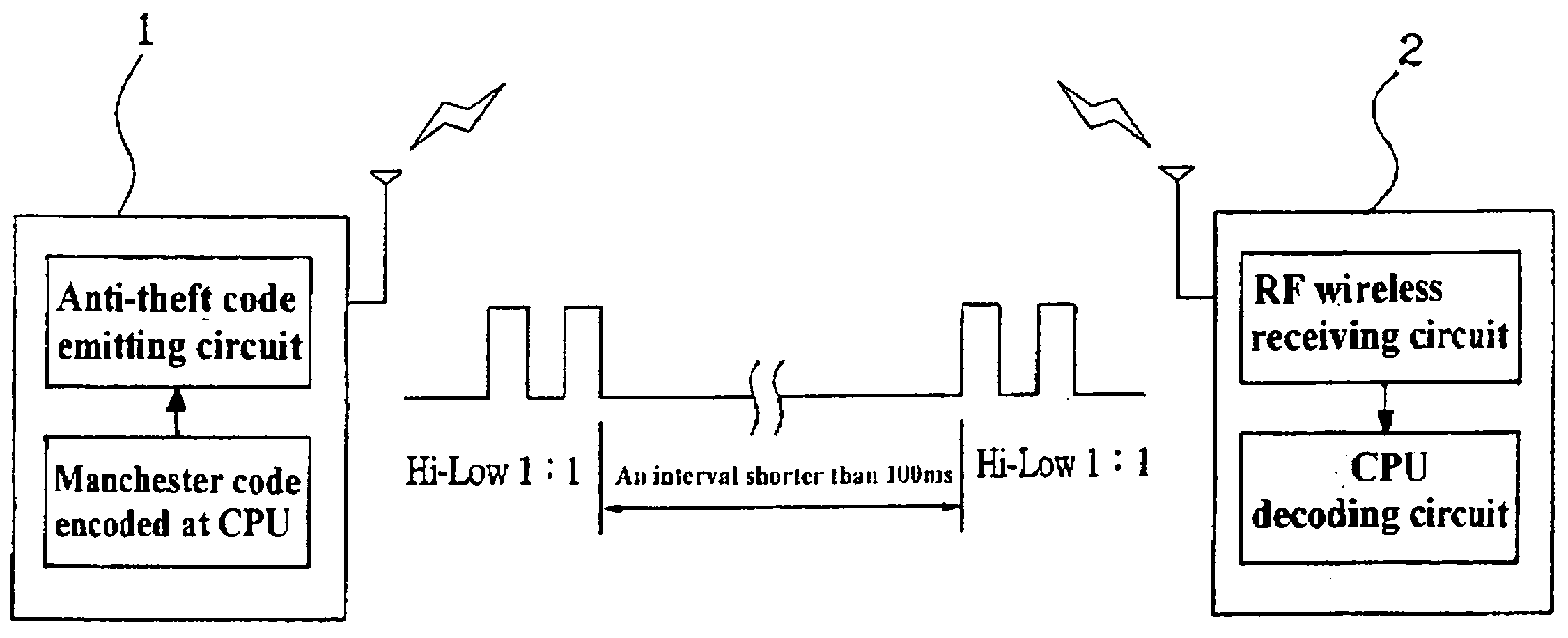
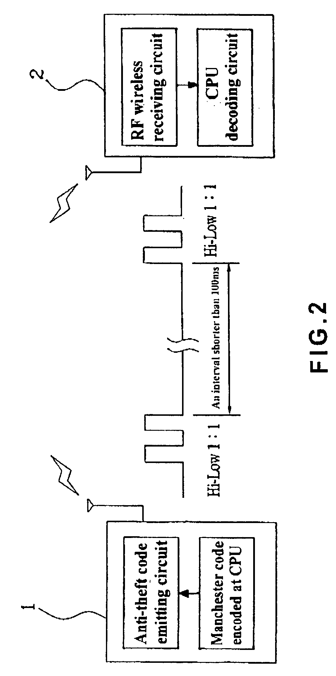
[0009] To achieve the above and other objects of the present invention, the wireless anti-theft device of the present invention mainly includes a host having a power-supply voltage-stabilizing circuit, an anti-theft coding and CPU circuit, a host control circuit, an emitting circuit, a host receiving circuit, and an I / O socket; and a wireless siren being internally provided with a power-supply voltage-stabilizing circuit, an RF wireless receiving circuit, a decoding and CPU circuit, and an anti-theft voicing and driving circuit. The anti-theft coding and CPU circuit generates Manchester anti-theft code, a Hi-Low ratio of which is 1:1, so that the wireless siren could quickly and accurately analyze any received data code to emit precise warning sound.

Problems solved by technology

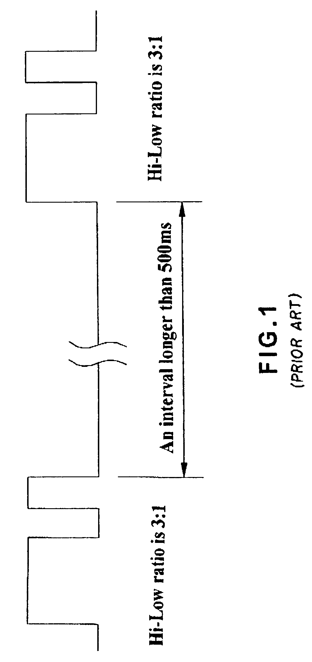
To prevent exhaust and wastewater from flowing into the car via wire mounting holes on the fire wall, most car manufacturers would seal these holes after the wiring of the car is completed, or purposefully provide an S-shaped fire wall, resulting in high difficulties in extending the wires of the anti-theft device through the fire wall and increased installation time and labor.
And, it would inevitably spoil or damage the original airtight and watertight ability of the fire wall as well as the wires originally provided with the car, if the wires of the anti-theft device are forced through the fire wall.
All these ways of extending through the fire wall will result in incomplete airtight and watertight ability of the fire wall, and increased installation time and labor.
Particularly, most newly designed cars in the market have a double-layer fire wall that further increases the difficulty in wiring the anti-theft device.
Even if the drilled holes on the fire wall may be sealed again, they would adversely affect an overall appearance of the car body.
And, most car buyers would not accept such defects on a new car.
However, to distinguish the coded signals of the anti-theft device from noises on the wiring of the car, a relatively complicate circuitry for data analysis and data control must be provided, which results in largely increased cost to lower the consumers' interest in buying the car.
That is, the conventional wireless anti-theft device has the problem of indicating incorrect functions.

Method used


Image

  • Wireless anti-theft device
  • Wireless anti-theft device
  • Wireless anti-theft device

Examples


Embodiment Construction

[0017] Please refer to FIGS. 2 to 4, in which a wireless anti-theft device according to the present invention is shown. The wireless anti-theft device of the present invention mainly includes a host 1 and a wireless siren 2.

[0018] The host 1 includes a power-supply voltage-stabilizing circuit 11 for supplying power to different components of the host 1, an anti-theft coding and CPU circuit 12 for generating a Manchester anti-theft code having a Hi-Low ratio of 1:1, a host control circuit 13 for controlling the operation of different components of the host, an emitting circuit 14 for emitting an anti-theft signal, a host receiving circuit 15 for receiving a remote controlling signal, and an input / output (I / O) socket 16 for electrically connecting to a power receptacle on a car.

[0019] The wireless siren 2 is internally provided with a power-supply voltage-stabilizing circuit 21 for supplying power to different components of the wireless siren 2, an RF wireless receiving circuit 24 f...


PUM


Abstract

A wireless anti-theft device mainly includes a host having a power-supply voltage-stabilizing circuit, an anti-theft coding and CPU circuit, a host control circuit, an emitting circuit, a host receiving circuit, and an I / O socket; and a wireless siren being internally provided with a power-supply voltage-stabilizing circuit, an RF wireless receiving circuit, a decoding and CPU circuit, and an anti-theft voicing and driving circuit. The anti-theft coding and CPU circuit generates Manchester anti-theft code having a Hi-Low ratio of 1:1, so that the wireless siren could quickly and accurately analyze received data code to emit precise warning sound.

Description

FIELD OF THE INVENTION [0001] The present invention relates to a wireless anti-theft device, and more particularly to a wireless anti-theft device that uses Manchester code having a Hi-Low ratio of 1:1 to transmit data code, so that a wireless siren controlled by a host of the device is able to quickly and accurately analyze the received data code to emit precise warning sound without interfering with or being interfered by other similar devices. BACKGROUND OF THE INVENTION [0002] Most currently commercially available car anti-theft devices may be divided into two types according to the manner of installation thereof. The first type includes a host that is mounted in a car. In this case, an output wire for an anti-theft speaker of the device is extended from an interior of the car through a steel fire wall into an engine chamber of the car. The second type includes a host that is mounted in the engine chamber of a car. In this second case, door open / close wires and other in-car dete...

Claims


Application Information

Patent Timeline
Patent Type & Authority Applications(United States)
IPC IPC(8): B60R25/10
CPCB60R25/104B60R25/1003
Inventor CHEN, TSE-HSING
Owner LU SHU CHEN
Learn More