
Receiver, signal demodulation module and demodulation method thereof

a receiver and signal demodulation technology, applied in the field of receivers, can solve the problems of low power efficiency and high energy efficiency, limited power source from the outside, and low overall power efficiency and energy efficiency, and achieve the effects of simplifying circuit design, reducing circuit design costs, and raising sensitivities and energy efficiency of receivers

Active Publication Date: 2014-08-19
NAT TAIWAN UNIV
View PDF1 Cites 0 Cited by
  • Summary
  • Abstract
  • Description
  • Claims
  • Application Information

AI Technical Summary

Benefits of technology

The patent text describes a new technology that prevents a problem in previous devices called the "pulling effect" and improves the sensitivity and energy efficiency of a receiver. This is done by using a new method that converts the phase change of a modulation signal into an amplitude change. This new technology also simplifies the design of the circuit and reduces the cost.

Problems solved by technology

However, it is quite strict when it comes to power efficiency, and with an application method of implantation, there is limited power source from the outside.
Therefore, it is a current issue in how to maintain an overall low power efficiency and high energy efficiency, and to keep a specific transmission distance and amount of data needed.
Furthermore, it is able to demodulate Binary Phase Shift Keying (BPSK) with the method in prior arts that is to demodulate with the two injection-locked oscillators; however, there is no absolute reference phase in the demodulation mechanism, and thus it is possible to cause a series of mistakes when a mistake happens, and thus leads to a high Bit Error Rate (BER).

Method used


Image

  • Receiver, signal demodulation module and demodulation method thereof
  • Receiver, signal demodulation module and demodulation method thereof
  • Receiver, signal demodulation module and demodulation method thereof

Examples


Embodiment Construction

[0029]The aforementioned illustrations and following detailed descriptions are exemplary for the purpose of further explaining the scope of the instant disclosure. Other objectives and advantages related to the instant disclosure will be illustrated in the subsequent descriptions and appended drawings. In the drawings, the size and relative sizes of layers and regions may be exaggerated for clarity.

[0030]It will be understood that, although the terms first, second, third, and the like, may be used herein to describe various elements, components, regions, layers and / or sections, these elements, components, regions, layers and / or sections should not be limited by these terms. These terms are only to distinguish one element, component, region, layer or section from another region, layer or section discussed below could be termed a second element, component, region, layer or section without departing from the teachings of the instant disclosure. As used herein, the term “and / or” include...


PUM


Abstract

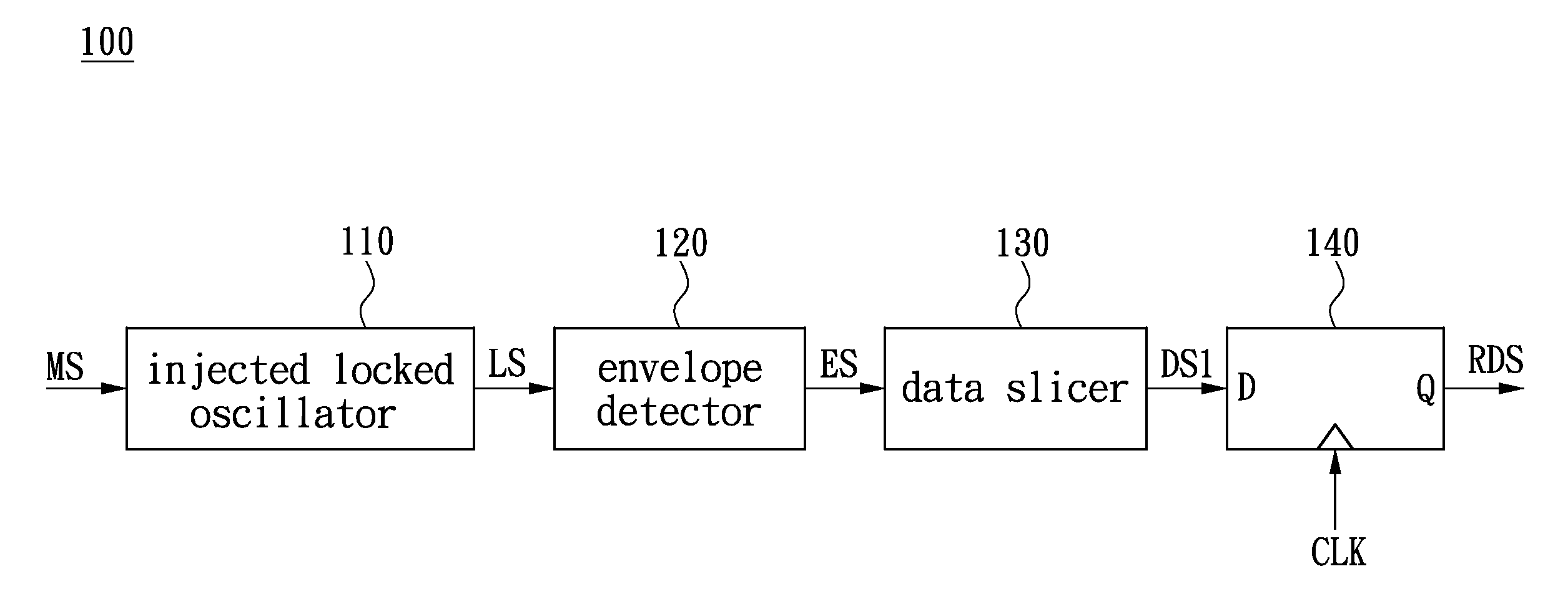
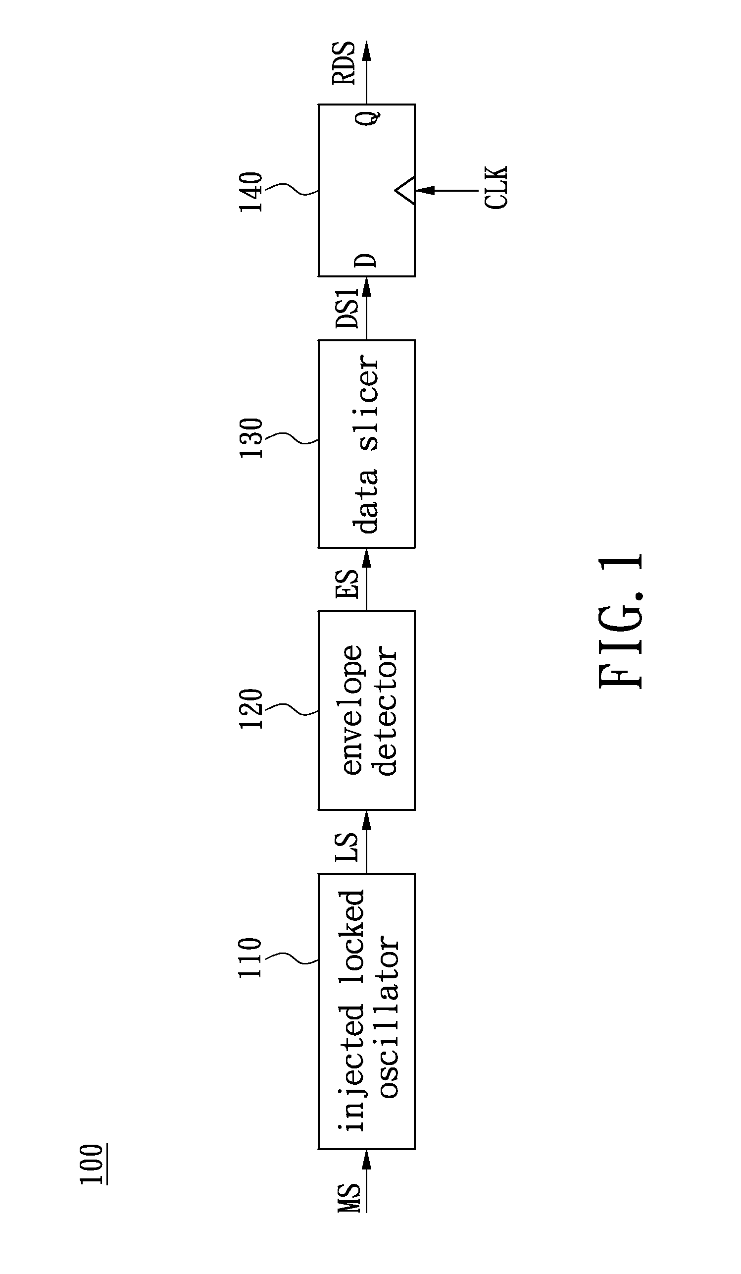
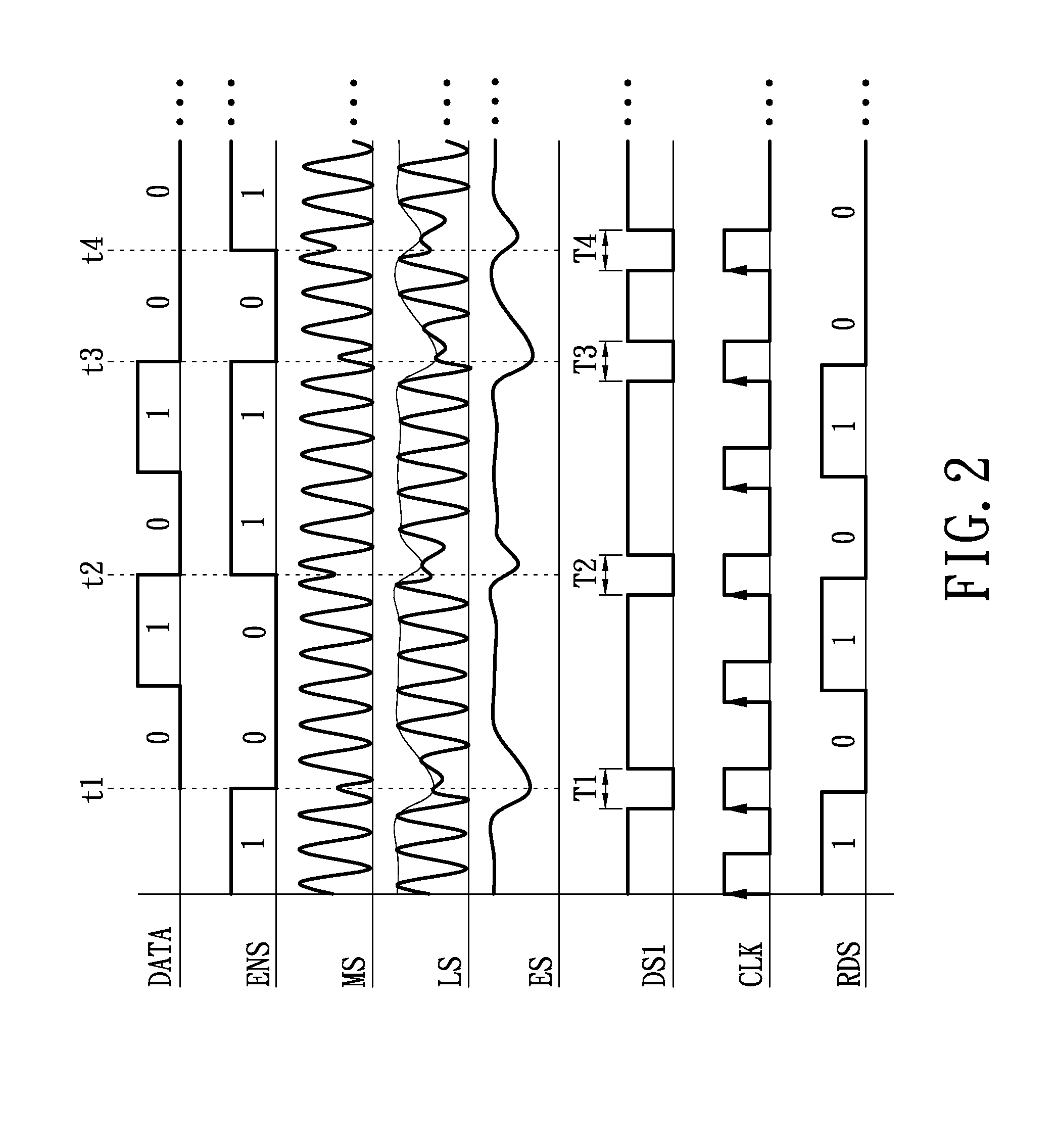
A signal demodulation module is disclosed. The signal demodulation module includes an injection-locked oscillator, an envelope detector and a data slicer. The injection-locked oscillator has a central oscillating frequency equal to a frequency of a digital modulation signal received, and outputs a phase-locked oscillating signal which is in phase to the digital modulation signal. When input phase of the digital modulation signal changes, output phase of the injection-locked oscillator changes synchronously. The envelope detector is used for detecting an envelope line of the phase-locked oscillating signal and outputting an envelope signal accordingly. The data slicer is used for receiving the envelop signal and outputting a first digital signal according to a reference voltage and the envelop signal.

Description

BACKGROUND OF THE DISCLOSURE[0001]1. Field of the Disclosure[0002]The instant disclosure relates to a receiver; in particular, to a signal demodulation module for a receiver.[0003]2. Description of Related Art[0004]As people should know, communication includes wire / wireless communication supported by wire / wireless communication equipment. Communication systems include domestic / international cellular telecommunication system, Internet, and point-to-point indoor wireless network. Each type of the communication systems is constructed and operated according to one or a plurality of communication standard. For example, wireless communication may be operated according to one or a plurality of standard such as Institute of Electrical and Electronics Engineers (IEEE) 802.11, Bluetooth, Advanced Mobile Phone System (AMPS), digital AMPS, Global System for Mobile Communications (GSM), Code Division Multiple Access (CDMA), local multi-point distribution systems (LMDS), multi-channel-multi-point...

Claims


Application Information

Patent Timeline
Patent Type & Authority Patents(United States)
IPC IPC(8): H03D3/00H04L27/227
CPCH04L27/2272H04L27/2071
Inventor TSAI, YI-LINCHEN, JIAN-YOUWANG, BANG-CYUANLIN, TSUNG-HSIEN
Owner NAT TAIWAN UNIV
Learn More