Charging arrangement for a vehicle

Active Publication Date: 2012-12-13
PEIKER ACUSTIC GMBH & CO KG
View PDF1 Cites 23 Cited by
  • Summary
  • Abstract
  • Description
  • Claims
  • Application Information

AI Technical Summary

Benefits of technology

[0014]In particular, the invention provides for the output device to signal the direction in which the primary coil should be moved in order to improve the efficiency of the inductive transmission of electrical energy. According to the invention, this is best done by two or four direction indications, depending on the number of movement axes.
[0015]In another embodiment, the charging arrangement further comprises an inductively chargeable mobile electronic appliance having a secondary coil, charging electronics and a rechargeable battery, and a charging device having a primary coil and a charging surface which is associated with the primary coil, with the secondary coil being arranged in a fixed position in the mobile electronic appliance. Furthermore, the charging arrangement comprises a holding device in which the mobile electronic appliance is held, and with the mobile electronic appliance being fixable in the holding device relative to the charging surface of the charging device selectively in a first shaking-resistant secondary position and at least one second shaking-resistant secondary position, or with the mobile electronic appliance being fixable together with the holding device relative to the charging surface of the charging device selectively in a first shaking-resistant secondary position and in at least one second shaking-resistant secondary position. Such fixing of the secondary coil and of the mobile electronic appliance in different secondary positions allows the efficiency of the energy transmission for different mobile electronic appliances to be optimized even when the primary coil is stationary.
[0016]According to another embodiment of the invention, the mobile electronic appliance can be moved in the holding device in at least one spatial direction from the first secondary position to the further secondary positions, or the mobile electronic appliance can be moved together with the holding device in at least one spatial direction from the first secondary position to the further secondary positions. This makes it p

Problems solved by technology

A charging appliance such as this cannot guarantee that energy is always transmitted with the same efficiency, because of the shak

Method used


Image

  • Charging arrangement for a vehicle
  • Charging arrangement for a vehicle
  • Charging arrangement for a vehicle

Examples


Example

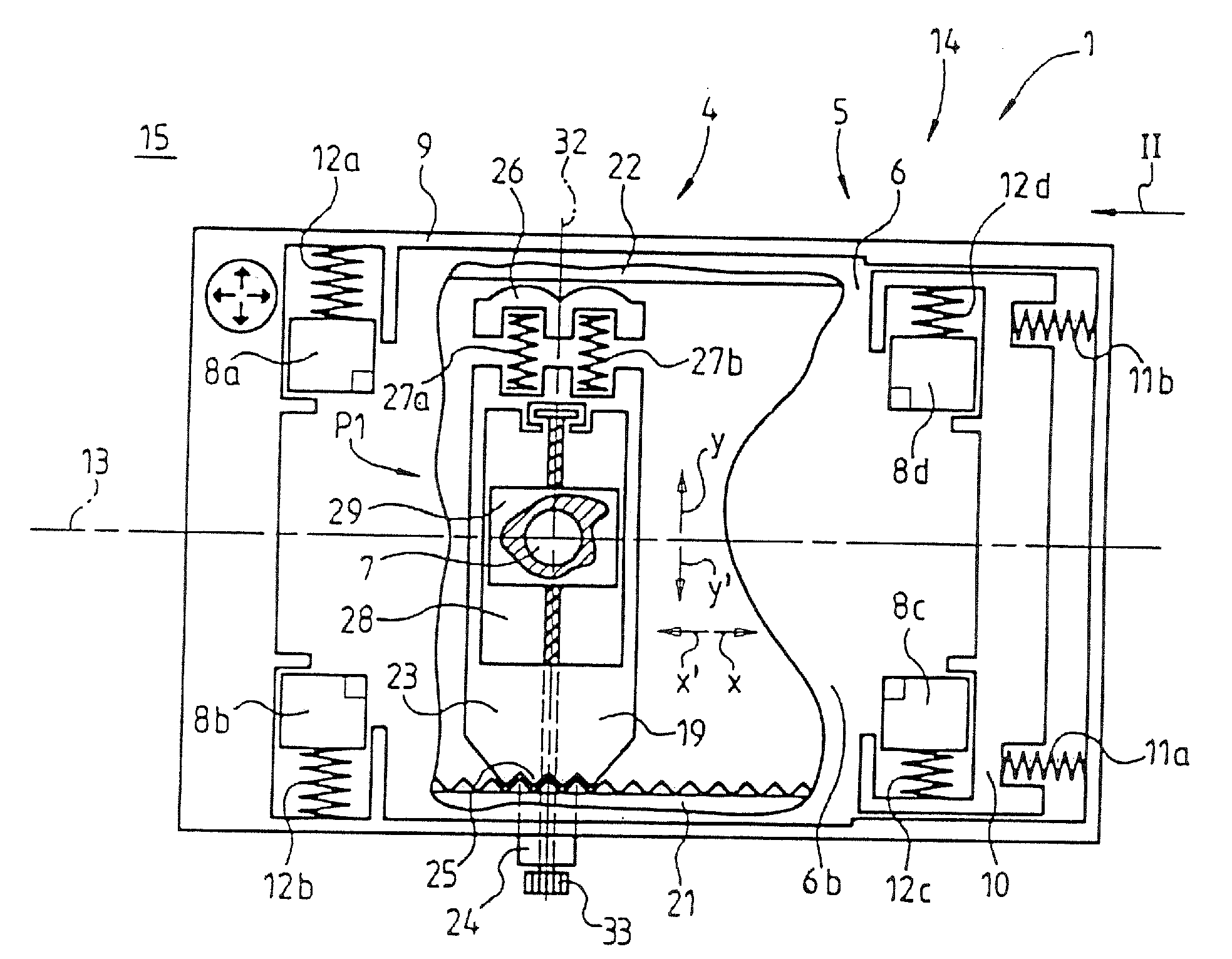
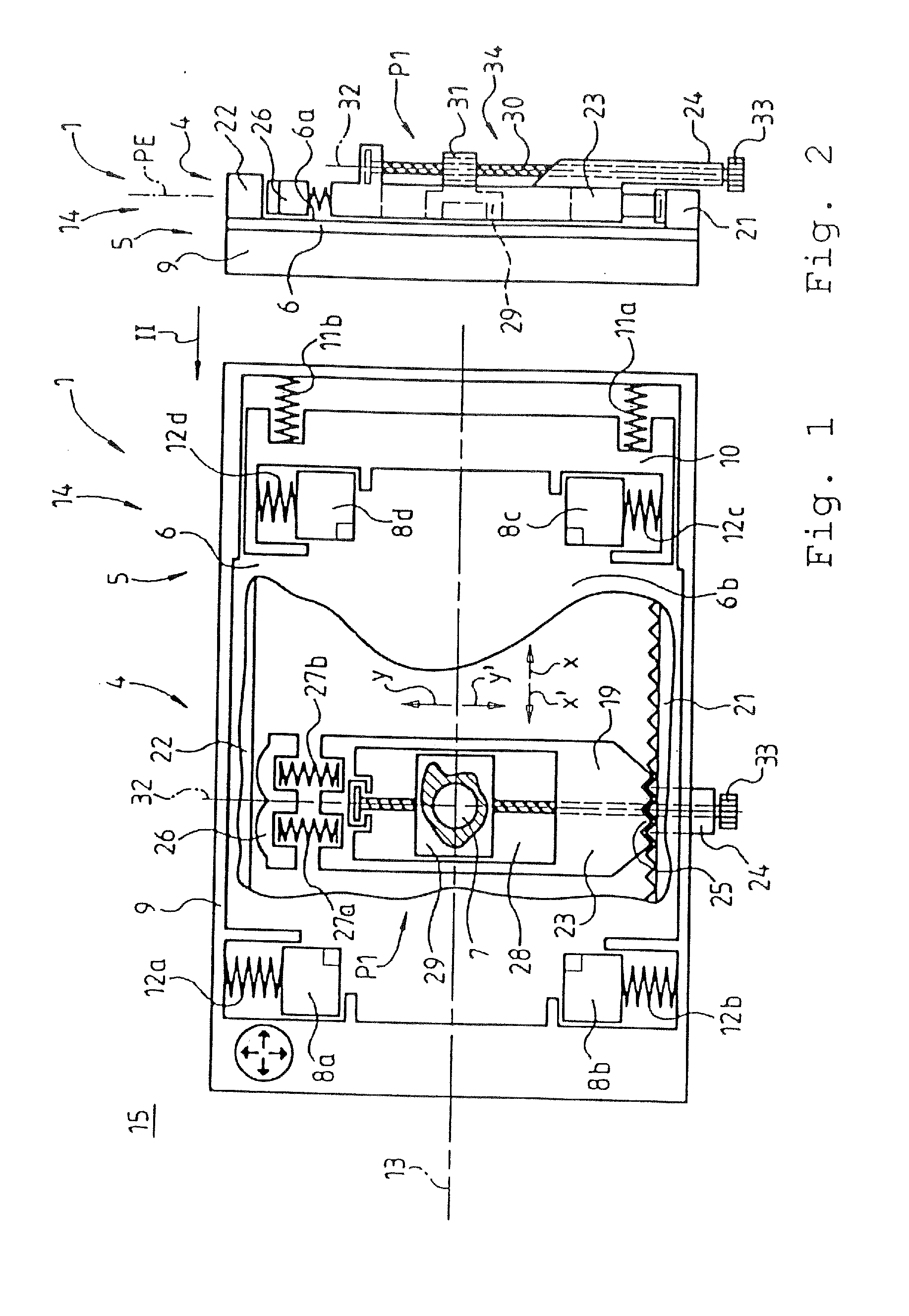
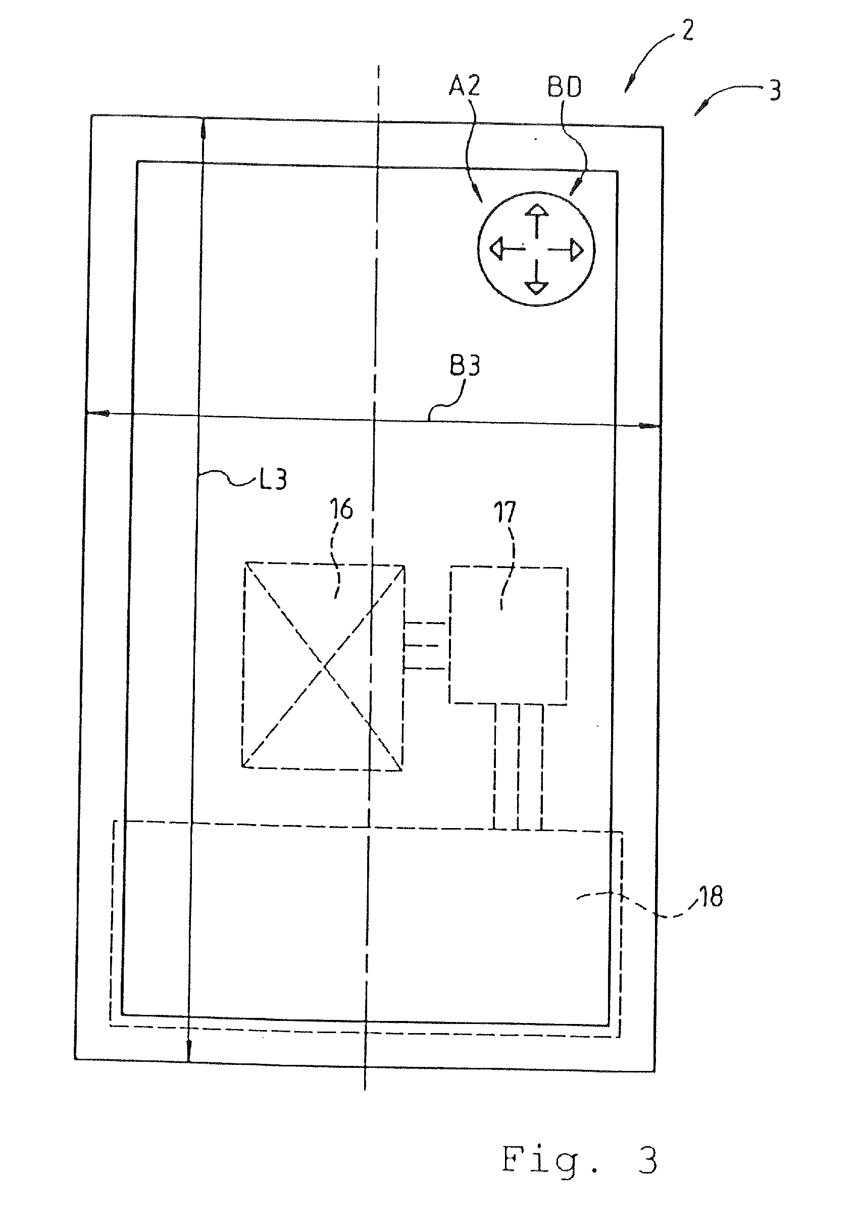
[0038]FIG. 1 shows a plan view of a charging arrangement 1 without a mobile electronic appliance. FIG. 3 shows a plan view of a mobile electronic appliance 2 which is intended to be inserted into the charging arrangement 1, with the mobile electronic appliance 2 being in the form of a mobile telephone 3. The charging arrangement 1 shown in FIG. 1 comprises a charging device 4 and a holding device 5. Essentially, of the charging device 4, a charging surface 6 and a primary coil 7 in the area of the charging surface 6 which is illustrated cut away are disclosed. The holding device 4 which holds the mobile telephone 3 illustrated in FIG. 3 comprises four holding jaws 8a to 8d, which are mounted in a sprung manner. In this case, the holding jaws 8a and 8b are supported with respect to a frame 9 of the holding device 5, and the holding jaws 8c and 8d are supported on a link 10 which is supported on the frame 9 in the arrow direction x by spring elements 11a, 11b. The holding jaws 8a to 8...


PUM


Abstract

The invention relates to a charging arrangement for a vehicle comprising an inductively chargeable mobile electronic appliance consisting of a multiplicity of different, inductively chargeable, mobile electronic appliances, having a secondary coil, charging electronics and a rechargeable battery and a charging device having a primary coil and a charging surface which is associated with the primary coil and above which the mobile electronic appliance can be placed down for charging. In this case, the primary coil can be fixed in a first primary position and in at least one second primary position on a primary plane relative to the charging surface, with the primary coil being fixed in the chosen primary position independently of shaking, vibrations or centrifugal forces acting on the charging arrangement, and independently of the presence of the mobile electronic appliance.

Description

[0001]This application claims the benefit under 35 USC §119(a)-(d) of German Application Nos. 10 2011 104 990.1 and 10 2011 110 680.8 having filing dates of Jun. 8, 2011 and Aug. 19, 2011, respectively, the entireties of which are incorporated herein by reference.FIELD OF THE INVENTION[0002]The invention relates to a charging arrangement for a vehicle comprising an inductively chargeable mobile electronic appliance.BACKGROUND OF THE INVENTION[0003]DE 10 2010 014 654 A1 discloses an inductive charging appliance which, for wire-free charging of different, portable electronic units, comprises a charging surface and a primary coil, with the mobile electronic unit being placed down for charging on the charging surface, and with the primary coil being mounted such that it can be moved in an internal compartment and being positioned and held by magnetic force. A charging appliance such as this cannot guarantee that energy is always transmitted with the same efficiency, because of the shaki...

Claims


Application Information

Patent Timeline
IPC IPC(8): H02J7/00
CPCH02J7/0044H02J7/025H02J7/0047H02J50/90H02J50/10
Inventor PEIKER, ANDREAS
Owner PEIKER ACUSTIC GMBH & CO KG
Why Eureka
Try Eureka